NETWORKING CXPI COMMUNICATION SYSTEM B12A0 Lost Communication with Illumination Module "A" B12A1 Lost Communication with Illumination Module "B"
DESCRIPTION
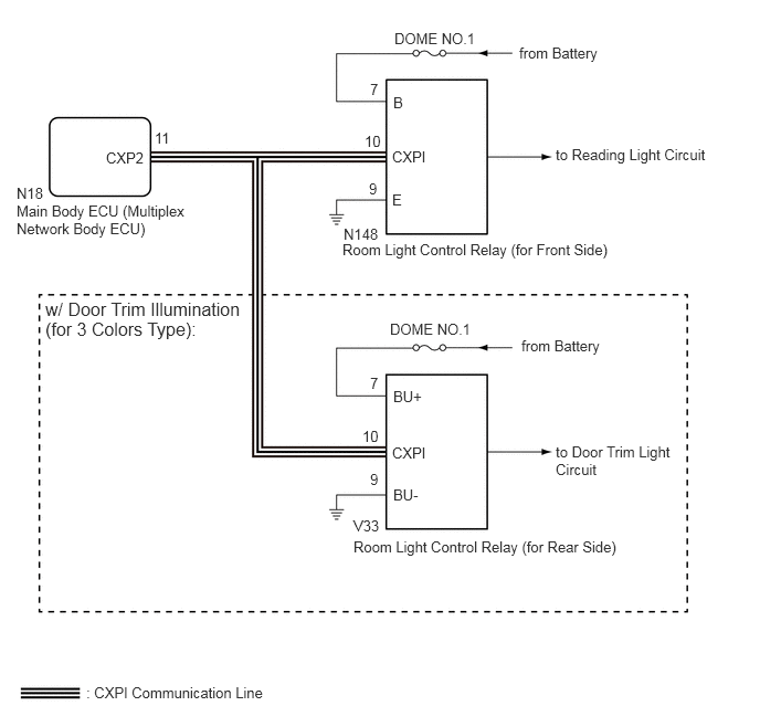
This DTC is stored when CXPI communication between the room light control relay and main body ECU (multiplex network body ECU) stops for 10 seconds or more.
| DTC No. | Detection Item | DTC Detection Condition | Trouble Area |
|---|---|---|---|
| B12A0 | Lost Communication with Illumination Module "A" | No communication between main body ECU (multiplex network body ECU) and room light control relay (for Front Side) for 10 seconds or more | ·
Main body ECU (multiplex network body ECU) ·
Room light control relay (for Front Side) ·
Harness or connector |
| B12A1 | Lost Communication with Illumination Module "B" | No communication between main body ECU (multiplex network body ECU) and room light control relay (for Rear Side) for 10 seconds or more | ·
Main body ECU (multiplex network body ECU) ·
Room light control relay (for Rear Side) ·
Harness or connector |
WIRING DIAGRAM
CAUTION / NOTICE / HINT
- NOTICE:
- ·
Inspect the fuses for circuits related to this system before performing the following procedure.
·Recognition code registration is necessary when replacing the main body ECU (multiplex network body ECU).
·If the main body ECU (multiplex network body ECU) is replaced, refer to the Service Bulletin.
·When disconnecting and reconnecting the battery.
- HINT:
-
When disconnecting and reconnecting the battery, there is an automatic learning function that completes learning when the respective system is used.
·Some parts must be initialized and set when replacing or removing and installing parts.
PROCEDURE
Clear the DTCs.
- Body Electrical > Main Body > Clear DTCs
- 50002 123
Check for DTCs.
- Body Electrical > Main Body > Trouble Codes
- 50001 123
- Result:
Result Proceed to DTC B12A0 and B12A1 are output A DTC B12A0 is output B DTC B12A1 is output C
A
B
C
Disconnect the cable from the negative (-) battery terminal.
Disconnect the N148 room light control relay (for Front Side) connector.
Disconnect the V33 room light control relay (for Rear Side) connector.
Disconnect the N18 main body ECU (multiplex network body ECU) connector.
Measure the resistance according to the value(s) in the table below.
- Standard Resistance:
Tester Connection Condition Specified Condition N148-10 (CXPI) - N18-11 (CXP2) Cable disconnected from negative (-) battery terminal Below 1 Ω N148-10 (CXPI) - Body ground Cable disconnected from negative (-) battery terminal 10 kΩ or higher
- Result:
Proceed to OK NG
OK
for LHD: Click herePower Source / Network>POWER DISTRIBUTION>MAIN BODY ECU (for LHD)>REMOVAL201906,999999,_57,_079061,_0383489,RM100000001IVKI,
for RHD: Click herePower Source / Network>POWER DISTRIBUTION>MAIN BODY ECU (for RHD)>REMOVAL201906,999999,_57,_079061,_0383490,RM100000001IVRX,
NG
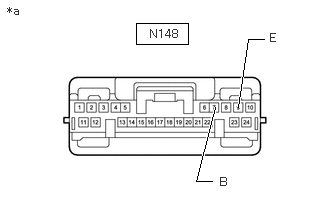
| *a | Front view of wire harness connector
(to Room Light Control Relay [for Front Side]) |
Disconnect the room light control relay (for Front Side) connector.
Measure the resistance according to the value(s) in the table below.
- Standard Resistance:
Tester Connection Condition Specified Condition N148-9 (E) - Body ground Always Below 1 Ω
Measure the voltage according to the value(s) in the table below.
- Standard Voltage:
Tester Connection Condition Specified Condition N148-7 (B) - Body ground Always 10 to 14 V
- Result:
Proceed to OK NG
OK
NG
Turn the ignition switch off.
Disconnect the cable from the negative (-) battery terminal.
Disconnect the N18 main body ECU (multiplex network body ECU) connector.
Disconnect the N148 room light control relay (for Front Side) connector.
w/ Door Trim Illumination (for 3 Colors Type):
Disconnect the V33 room light control relay (for Rear Side) connector.
Measure the resistance according to the value(s) in the table below.
- Standard Resistance:
Tester Connection Condition Specified Condition N148-10 (CXPI) - N18-11 (CXP2) Cable disconnected from negative (-) battery terminal Below 1 Ω N148-10 (CXPI) - Body ground Cable disconnected from negative (-) battery terminal 10 kΩ or higher
- Result:
Proceed to OK NG
OK
NG
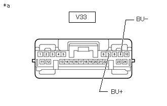
| *a | Front view of wire harness connector
(to Room Light Control Relay [for Rear Side]) |
Disconnect the room light control relay (for Rear Side) connector.
Measure the resistance according to the value(s) in the table below.
- Standard Resistance:
Tester Connection Condition Specified Condition V33-9 (BU-) - Body ground Always Below 1 Ω
Measure the voltage according to the value(s) in the table below.
- Standard Voltage:
Tester Connection Condition Specified Condition V33-7 (BU+) - Body ground Always 10 to 14 V
- Result:
Proceed to OK NG
OK
NG
Turn the ignition switch off.
Disconnect the cable from the negative (-) battery terminal.
Disconnect the N18 main body ECU (multiplex network body ECU) connector.
Disconnect the N148 room light control relay (for Front Side) connector.
Disconnect the V33 room light control relay (for Rear Side) connector.
Measure the resistance according to the value(s) in the table below.
- Standard Resistance:
Tester Connection Condition Specified Condition V33-10 (CXPI) - N18-11 (CXP2) Cable disconnected from negative (-) battery terminal Below 1 Ω V33-10 (CXPI) - Body ground Cable disconnected from negative (-) battery terminal 10 kΩ or higher
- Result:
Proceed to OK NG
OK
NG