LIGHTING (EXT) LIGHTING SYSTEM(w/ Headlight ECU) Headlight Dimmer Switch Circuit
DESCRIPTION
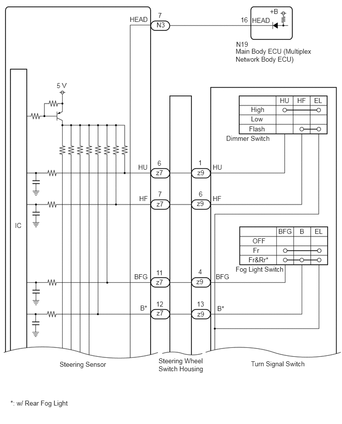
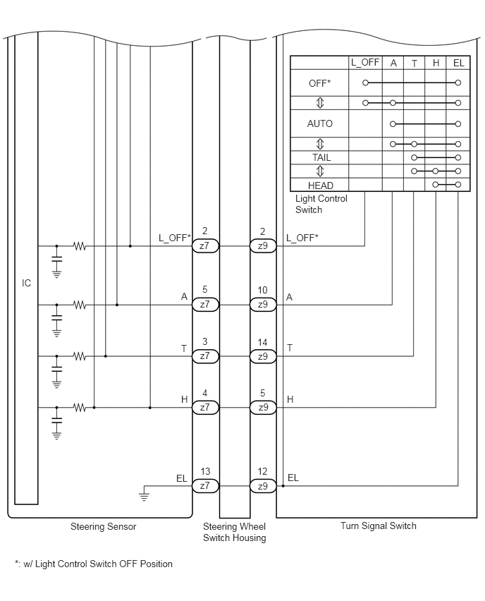
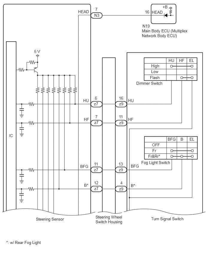
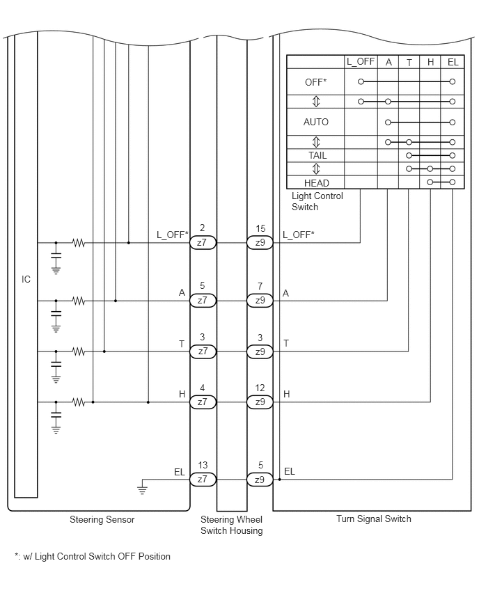
The steering sensor receives the following switch information:
Light control switch in OFF*1, TAIL, HEAD, AUTO position
Dimmer switch in High, Low or Flash position
Fog light switch in Fr, Fr&Rr*2 or off position
*1: w/ Light Control Switch OFF Position
*2: w/ Rear Fog Light
WIRING DIAGRAM
for LH Side Type
for RH Side Type
CAUTION / NOTICE / HINT
- NOTICE:
-
Before replacing the main body ECU (multiplex network body ECU), refer to Service Bulletin.
PROCEDURE
Connect the GTS to the DLC3.
Turn the engine switch on (IG).
Turn the GTS on.
Enter the following menus: Chassis / Steering Angle Sensor / Data List.
Read the Data List according to the display on the GTS.
- Chassis > Steering Angle Sensor > Data List
-
Tester Display Measurement Item Range Normal Condition Diagnostic Note Light OFF Switch Light control switch OFF position signal*1 OFF or ON OFF: Light control switch not in OFF position
ON: Light control switch in OFF position- Auto Light Switch Light control switch AUTO position signal OFF or ON OFF: Light control switch not in AUTO position
ON: Light control switch in AUTO position- Head Light Switch (Tail) Light control switch TAIL position signal OFF or ON OFF: Light control switch not in TAIL position
ON: Light control switch in TAIL position- Head Light Switch (Head) Light control switch HEAD position signal OFF or ON OFF: Light control switch not in HEAD position
ON: Light control switch in HEAD position- High Beam Main Switch Dimmer switch High position signal OFF or ON OFF: Dimmer switch not in High position
ON: Dimmer switch in High position- Passing Light Switch Dimmer switch Flash position signal OFF or ON OFF: Dimmer switch not in Flash position
ON: Dimmer switch in Flash position- Front Fog Light Switch Front fog light switch signal OFF or ON OFF: Fog light switch in OFF position
ON: Fog light switch in Fr position- Rear Fog Light/Bad Weather Switch Rear fog light switch signal*2 OFF or ON OFF: Fog light switch in OFF position
ON: Fog light switch in Fr&Rr position-
*1: w/ Light Control Switch OFF Position
*2: w/ Rear Fog Light
- Chassis > Steering Angle Sensor > Data List
-
Tester Display Light OFF Switch Auto Light Switch Head Light Switch (Tail) Head Light Switch (Head) High Beam Main Switch Passing Light Switch Front Fog Light Switch Rear Fog Light/Bad Weather Switch - 50003 417 1,2,3,4,5,6,11,12
- OK:
Normal conditions listed above are displayed.
- Result:
Proceed to OK NG
OK
NG
Connect the GTS to the DLC3.
Turn the engine switch on (IG).
Turn the GTS on.
Enter the following menus:
Chassis / Steering Angle Sensor / Data List.
Body Electrical / Main Body / Data List.
Read the Data List according to the display on the GTS.
- Chassis > Steering Angle Sensor > Data List
-
Tester Display Measurement Item Range Normal Condition Diagnostic Note Head Light Switch (Head) Light control switch HEAD position signal OFF or ON OFF: Light control switch not in HEAD position
ON: Light control switch in HEAD position-
- Body Electrical > Main Body > Data List
-
Tester Display Measurement Item Range Normal Condition Diagnostic Note Head Light SW (Head) Light control switch HEAD position signal OFF or ON OFF: Light control switch not in HEAD position
ON: Light control switch in HEAD position-
- Chassis > Steering Angle Sensor > Data List
-
Tester Display Head Light Switch (Head) - 50003 417 4
- Body Electrical > Main Body > Data List
-
Tester Display Head Light SW (Head) - 50003 123 59
- OK:
Normal conditions listed above are displayed.
- Result:
Result Proceed to OK A NG ("Steering Angle Sensor" side abnormality) B NG ("Main Body" side abnormality) C NG ("Steering Angle Sensor" and "Main Body" are abnormality) D
A
B
C
D
Disconnect the N19 main body ECU (multiplex network body ECU) connector.
Disconnect the N3 steering sensor connector.
Measure the resistance according to the value(s) in the table below.
- Standard Resistance:
Tester Connection Condition Specified Condition N3-7 (HEAD) - N19-16 (HEAD) Always Below 1 Ω N3-7 (HEAD) or N19-16 (HEAD) - Body ground Always 10 kΩ or higher
- Result:
Proceed to OK NG
OK
for LHD:
for RHD:
NG
Remove the turn signal switch.
Inspect the turn signal switch.
- Result:
Proceed to OK NG
OK
NG
Remove the steering wheel switch housing.
Inspect the steering wheel switch housing.
- Result:
Proceed to OK NG
OK
NG
Disconnect the N19 main body ECU (multiplex network body ECU) connector.
Disconnect the N3 steering sensor connector.
Measure the resistance according to the value(s) in the table below.
- Standard Resistance:
Tester Connection Condition Specified Condition N3-7 (HEAD) or N19-16 (HEAD) - Body ground Always 10 kΩ or higher
- Result:
Proceed to OK NG
OK
NG
Remove the turn signal switch.
Inspect the turn signal switch.
- Result:
Proceed to OK NG
OK
NG
Remove the steering wheel switch housing.
Inspect the steering wheel switch housing.
- Result:
Proceed to OK NG
OK
NG