HEATING / AIR CONDITIONING AIR CONDITIONING UNIT REMOVAL
CAUTION / NOTICE / HINT
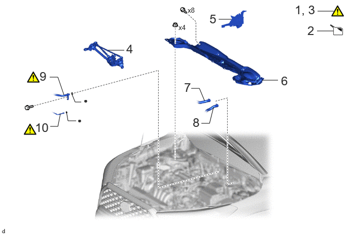
| Procedure | Part Name Code | 
|

|

|
|
|---|---|---|---|---|---|
| 1 | PRECAUTION | - | ( 202307,999999,_58,_104612,_0500007,RM100000002BK0Y_02_0173,) 202307,999999,_58,_104612,_0500007,RM100000002BK0Y_02_0173,)
|
- | - |
| 2 | DRAIN ENGINE COOLANT | - | - | (202307,999999,_58,_104612,_0500007,RM100000002BK0Y_02_0230,)
|
- |
| 3 | RECOVER REFRIGERANT FROM REFRIGERATION SYSTEM | - | (202307,999999,_58,_104612,_0500007,RM100000002BK0Y_02_0204,)
|
- | - |
| 4 | WINDSHIELD WIPER MOTOR AND LINK ASSEMBLY | - | - | - | - |
| 5 | NO. 1 HEATER AIR DUCT SPLASH SHIELD SEAL | 55737B | - | - | - |
| 6 | OUTER COWL TOP PANEL SUB-ASSEMBLY | 55701J | - | - | - |
| 7 | OUTLET HEATER WATER HOSE | - | - | - | - |
| 8 | INLET HEATER WATER HOSE | - | - | - | - |
| 9 | SUCTION PIPE SUB-ASSEMBLY | 88707 | (202307,999999,_58,_104612,_0500007,RM100000002BK0Y_02_0202,)
|
- | - |
| 10 | AIR CONDITIONING TUBE AND ACCESSORY ASSEMBLY | 88710E | (202307,999999,_58,_104612,_0500007,RM100000002BK0Y_02_0203,)
|
- | - |
| ● | Non-reusable part | - | - |
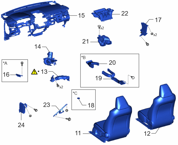
| Procedure | Part Name Code |
|
|
|
|
|---|---|---|---|---|---|
| 11 | FRONT SEAT ASSEMBLY LH | - | - | - | - |
| 12 | FRONT SEAT ASSEMBLY RH | - | - | - | - |
| 13 | NO. 1 AIR DUCT | 87211 | (202307,999999,_58,_104612,_0500007,RM100000002BK0Y_02_0229,)
|
- | - |
| 14 | STEERING COLUMN ASSEMBLY | - | - | - | - |
| 15 | INSTRUMENT PANEL SAFETY PAD SUB-ASSEMBLY | - | - | - | - |
| 16 | CLEARANCE WARNING ECU ASSEMBLY | 89340A | - | - | - |
| 17 | NO. 2 CONNECTOR HOLDER | 82666H | - | - | - |
| 18 | COOLER THERMISTOR (ROOM TEMPERATURE SENSOR) | 88625Q | - | - | - |
| 19 | NO. 2 CONSOLE BOX DUCT | 58862B | - | - | - |
| 20 | NO. 1 CONSOLE BOX DUCT | 58861B | - | - | - |
| 21 | CENTER HEATER TO REGISTER DUCT SUB-ASSEMBLY | 55086A | - | - | - |
| 22 | LOWER DEFROSTER NOZZLE ASSEMBLY | 55990B | - | - | |
| 23 | NO. 3 INSTRUMENT PANEL TO COWL BRACE SUB-ASSEMBLY | 55308B | - | - | - |
| 24 | INSTRUMENT PANEL JUNCTION BLOCK ASSEMBLY WITH MAIN BODY ECU | - | - | - | - |
| *A | w/ TOYOTA Parking Assist-sensor System | *B | w/ Rear Air Duct |
| *C | for Automatic Air Conditioning System | - | - |
| ● | Non-reusable part | - | - |
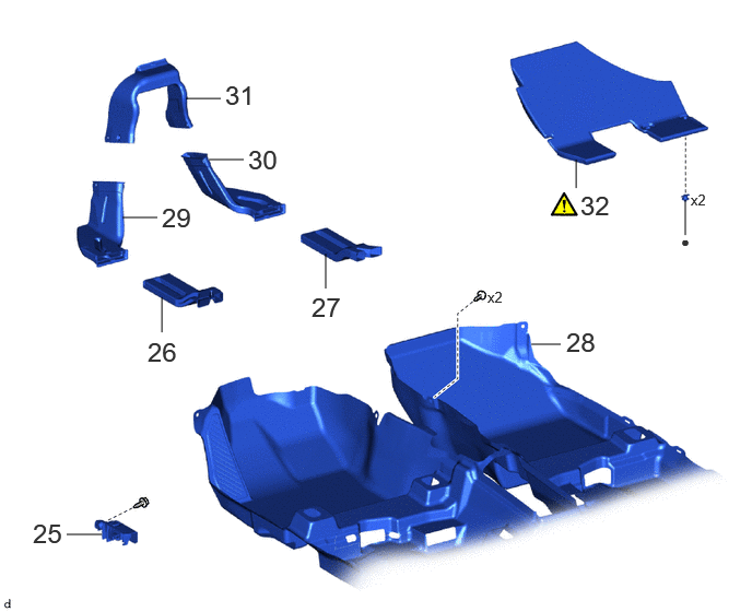
| Procedure | Part Name Code |
|
|
|
|
|---|---|---|---|---|---|
| 25 | FUEL LID LOCK OPEN LEVER SUB-ASSEMBLY | 77306 | - | - | - |
| 26 | NO. 3 REAR AIR DUCT | 87212G | - | - | - |
| 27 | NO. 5 REAR AIR DUCT | 87217C | - | - | - |
| 28 | FRONT FLOOR CARPET ASSEMBLY | 58510D | - | - | - |
| 29 | NO. 2 REAR AIR DUCT | 87213D | - | - | - |
| 30 | NO. 4 REAR AIR DUCT | 87212H | - | - | - |
| 31 | NO. 1 REAR AIR DUCT | 87212 | - | - | - |
| 32 | NO. 3 DASH PANEL INSULATOR PAD | 55215D | (202307,999999,_58,_104612,_0500007,RM100000002BK0Y_02_0246,)
|
- | - |
| ● | Non-reusable part | - | - |
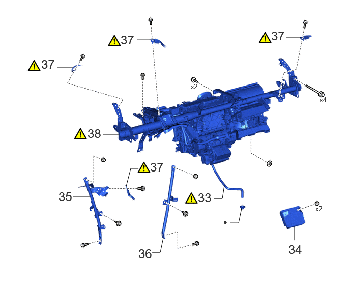
| Procedure | Part Name Code |
|
|
|
|
|---|---|---|---|---|---|
| 33 | DRAIN COOLER HOSE | 88539J | - | - | - |
| 34 | TELEMATICS TRANSCEIVER WITH BRACKET | - | - | - | - |
| 35 | NO. 1 INSTRUMENT PANEL BRACE SUB-ASSEMBLY | 55306A | - | - | - |
| 36 | NO. 2 INSTRUMENT PANEL BRACE SUB-ASSEMBLY | 55307C | - | - | - |
| 37 | INSTRUMENT PANEL WIRE | - | (202307,999999,_58,_104612,_0500007,RM100000002BK0Y_02_0243,)
|
- | - |
| 38 | INSTRUMENT PANEL REINFORCEMENT ASSEMBLY WITH AIR CONDITIONER UNIT ASSEMBLY | - | (202307,999999,_58,_104612,_0500007,RM100000002BK0Y_02_0240,)
|
- | - |
| ● | Non-reusable part | - | - |
| Procedure | Part Name Code |
|
|
|
|
|---|---|---|---|---|---|
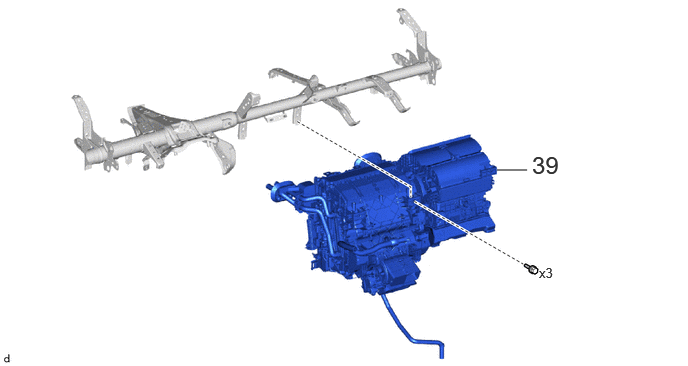
| 39 | AIR CONDITIONER UNIT ASSEMBLY | - | - | - | - |
CAUTION / NOTICE / HINT
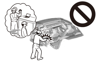
- CAUTION:
-
-
Some of these service operations affect the SRS airbag system. Read the precautionary notices concerning the SRS airbag system before servicing.
The necessary procedures (adjustment, calibration, initialization, or registration) that must be performed after parts are removed and installed, or replaced during air conditioning unit removal/installation are shown below.
| Replaced Part or Performed Procedure | Necessary Procedure | Effect/Inoperative Function when Necessary Procedure not Performed | Link |
|---|---|---|---|
·
No. 1 air conditioning radiator damper servo sub-assembly ·
No. 2 air conditioning radiator damper servo sub-assembly |
Initialize servo motor (Air Conditioning System) | DTCs are stored | for Gasoline Model with Automatic Air Conditioning System:(202307,999999,_58,_104612,_0601931,RM100000002BIKY,)
for Gasoline Model with Manual Air Conditioning System for Electrical Control Type:( 202307,999999,_58,_104612,_0601932,RM100000002BIMH,)
for HEV Model:( 202307,999999,_58,_104612,_0601796,RM100000002BI5X,)
|
- HINT:
-
When the cable is disconnected/reconnected to the auxiliary battery terminal, systems temporarily stop operating. However, each system has a function that completes learning the first time the system is used.
- ·
Learning completes when vehicle is driven
Effect/Inoperative Function When Necessary Procedures are not Performed Necessary Procedures Link *1: for Gasoline Model
Front camera system Drive the vehicle straight ahead at 15 km/h (10 mph) or more for 1 second or more. ( 202307,999999,_95,_112293,_0586709,RM100000002BSVY,)
Stop and start system*1 Drive the vehicle until stop and start control is permitted (approximately 5 to 60 minutes) ( 202307,999999,_51,_115233,_0510781,RM100000002CS0B,)
·Learning completes when vehicle is operated normally
Effect/Inoperative Function When Necessary Procedures are not Performed Necessary Procedures Link Power door lock control system
·Back door opener
Perform door unlock operation with door control switch or electrical key transmitter sub-assembly switch. ( 202201,999999,_58,_115226,_0510939,RM1000000020BSY,)
Power back door system Fully close the back door by hand.
- HINT:
-
Initialization is not necessary if the above procedures are performed while the back door is closed.
( 202201,999999,_59,_113746,_0504731,RM100000001ZJKP,)
Air conditioning system After the ignition switch is turned to ON, the servo motor standard position is recognized. -
PROCEDURE

 1. PRECAUTION
|
|
|
2.DRAIN ENGINE COOLANT
3.RECOVER REFRIGERANT FROM REFRIGERATION SYSTEM
4.REMOVE WINDSHIELD WIPER MOTOR AND LINK ASSEMBLY
55737B
5.REMOVE NO. 1 HEATER AIR DUCT SPLASH SHIELD SEAL
55701J
6.REMOVE OUTER COWL TOP PANEL SUB-ASSEMBLY
7.DISCONNECT OUTLET HEATER WATER HOSE

8.DISCONNECT INLET HEATER WATER HOSE

88707
9.DISCONNECT SUCTION PIPE SUB-ASSEMBLY
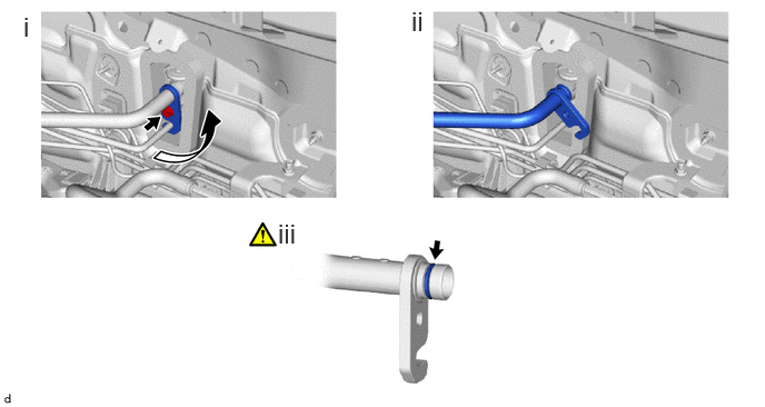
Remove the bolt and rotate the hook connector as shown in the illustration.
Disconnect the suction pipe sub-assembly.
Remove the O-ring from the suction pipe sub-assembly.
- NOTICE:
-
Seal the openings of the disconnected parts using vinyl tape to prevent entry of moisture and foreign matter.
88710E
10.DISCONNECT AIR CONDITIONING TUBE AND ACCESSORY ASSEMBLY
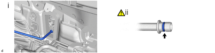
Disconnect the air conditioning tube and accessory assembly.
Remove the O-ring from the air conditioning tube and accessory assembly.
- NOTICE:
-
Seal the openings of the disconnected parts using vinyl tape to prevent entry of moisture and foreign matter.
11.REMOVE FRONT SEAT ASSEMBLY LH
12.REMOVE FRONT SEAT ASSEMBLY RH
Use the same procedure as for the LH side.
87211
13.REMOVE NO. 1 AIR DUCT
|
|
|
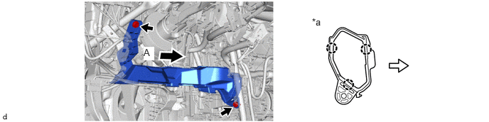
| *a | View A | - | - |

|
Front | - | - |
14.REMOVE STEERING COLUMN ASSEMBLY
15.REMOVE INSTRUMENT PANEL SAFETY PAD SUB-ASSEMBLY
89340A
16.REMOVE CLEARANCE WARNING ECU ASSEMBLY (w/ TOYOTA Parking Assist-sensor System)
82666H
17.REMOVE NO. 2 CONNECTOR HOLDER
88625Q
18.REMOVE COOLER THERMISTOR (ROOM TEMPERATURE SENSOR) (for Automatic Air Conditioning System)

58862B
19.REMOVE NO. 2 CONSOLE BOX DUCT (w/ Rear Air Duct)


|
Remove in this Direction (1) | 
|
Remove in this Direction (2) |
58861B
20.REMOVE NO. 1 CONSOLE BOX DUCT (w/ Rear Air Duct)
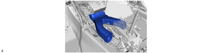
55086A
21.REMOVE CENTER HEATER TO REGISTER DUCT SUB-ASSEMBLY
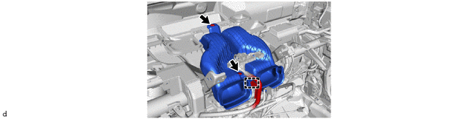
55990B
22.REMOVE LOWER DEFROSTER NOZZLE ASSEMBLY
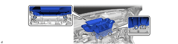
55308B
23.REMOVE NO. 3 INSTRUMENT PANEL TO COWL BRACE SUB-ASSEMBLY

24.REMOVE INSTRUMENT PANEL JUNCTION BLOCK ASSEMBLY WITH MAIN BODY ECU
77306
25.REMOVE FUEL LID LOCK OPEN LEVER SUB-ASSEMBLY
87212G
26.REMOVE NO. 3 REAR AIR DUCT

87217C
27.REMOVE NO. 5 REAR AIR DUCT

58510D
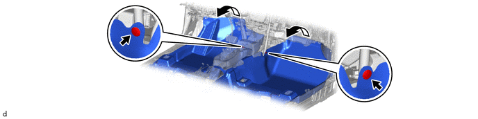
28.SEPARATE FRONT FLOOR CARPET ASSEMBLY
87213D
29.REMOVE NO. 2 REAR AIR DUCT

87212H
30.REMOVE NO. 4 REAR AIR DUCT

87212
31.REMOVE NO. 1 REAR AIR DUCT

55215D
32.REMOVE NO. 3 DASH PANEL INSULATOR PAD

| *a | Cut | - | - |
Cut each claw of the 2 clips to remove the No. 3 dash panel insulator pad.
- NOTICE:
-
If the No. 3 dash panel insulator pad is damaged, replace it with a new one.
Remove the 2 clips.
88539J
33.DISCONNECT DRAIN COOLER HOSE
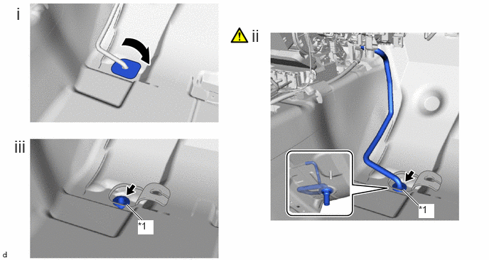
| *1 | Cooler Unit Drain Hose Grommet | - | - |
Turn back the front floor mat as shown in the illustration.
Disconnect the drain cooler hose.
- NOTICE:
-
If the drain cooler hose is disconnected from the cooler unit drain hose grommet, make sure to replace the cooler unit drain hose grommet with a new one. Failure to do so may lead to water ingress.
Remove the cooler unit drain hose grommet.
34.REMOVE TELEMATICS TRANSCEIVER WITH BRACKET
55306A
35.REMOVE NO. 1 INSTRUMENT PANEL BRACE SUB-ASSEMBLY
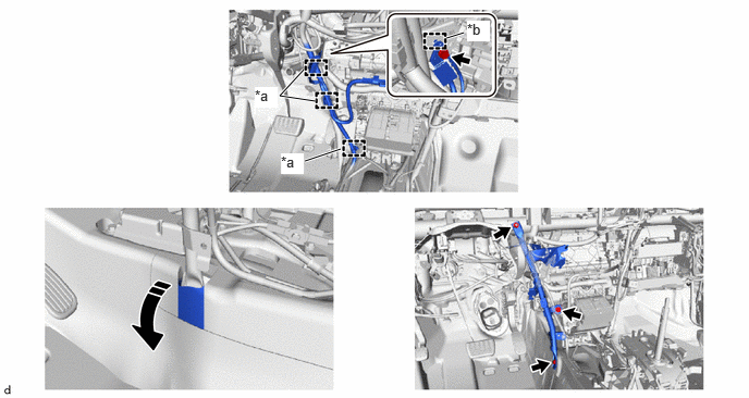
| *a | Clamp | *b | Guide |
|
|
Move in this Direction | - | - |
55307C
36.REMOVE NO. 2 INSTRUMENT PANEL BRACE SUB-ASSEMBLY
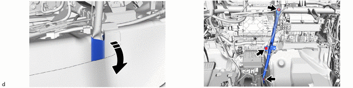
|
|
Move in this Direction | - | - |
37.DISCONNECT INSTRUMENT PANEL WIRE
|
|
|
- HINT:
-
The illustrations are representative examples, and details may differ.
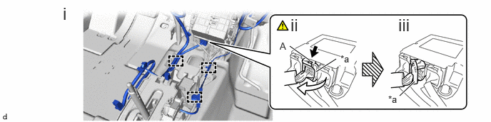
| *a | Lock lever | - | - |

|
Push down |
|
Release |
Disengage the clamps.
Push down the part (A) to release the lock lever.
Raise the lock lever to disconnect the connector.
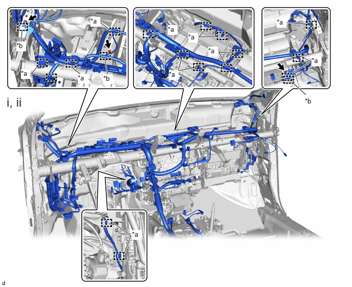
| *a | Clamp | *b | Guide |
Remove the 3 bolts.
Disengage the clamps and guides to disconnect the instrument panel wire.
38.REMOVE INSTRUMENT PANEL REINFORCEMENT ASSEMBLY WITH AIR CONDITIONER UNIT ASSEMBLY
|
|
|
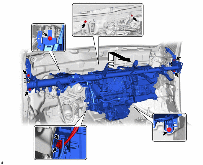
|
|
Remove in this Direction | - | - |
39.REMOVE AIR CONDITIONER UNIT ASSEMBLY