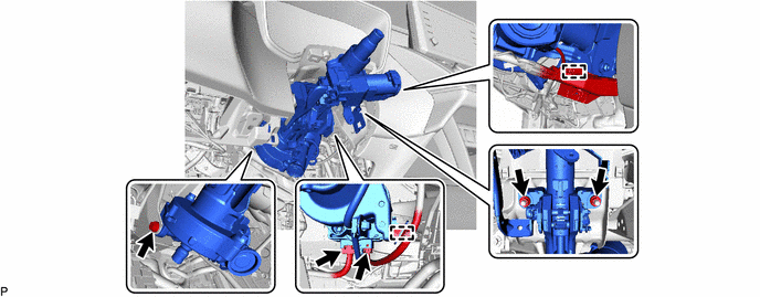
STEERING COLUMN STEERING COLUMN ASSEMBLY REMOVAL
CAUTION / NOTICE / HINT
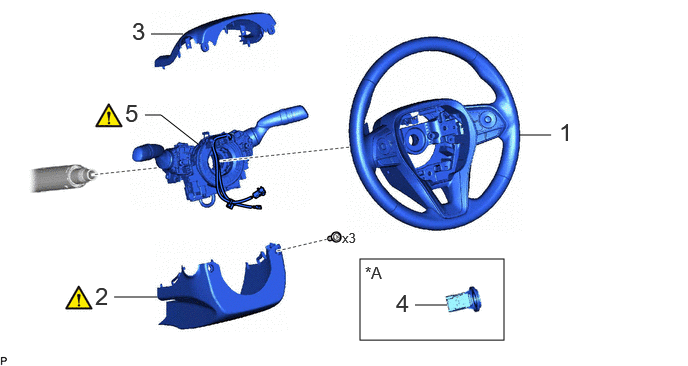
| Procedure | Part Name Code | 
|

|

|
|
|---|---|---|---|---|---|
| 1 | STEERING WHEEL ASSEMBLY | 45100 | - | - | - |
| 2 | LOWER STEERING COLUMN COVER | 45287 | ( 202307,999999,_55,_112306,_0501031,RM100000002C3MR_01_0114,) 202307,999999,_55,_112306,_0501031,RM100000002C3MR_01_0114,)
|
- | - |
| 3 | UPPER STEERING COLUMN COVER | 45286B | - | - | - |
| 4 | TRANSPONDER KEY COIL | 89782 | - | - | - |
| 5 | TURN SIGNAL SWITCH ASSEMBLY WITH SPIRAL CABLE SUB-ASSEMBLY | - | (202307,999999,_55,_112306,_0501031,RM100000002C3MR_01_0007,)
|
- | - |
| *A | w/o Smart Entry and Start System | - | - |

| Procedure | Part Name Code |
|
|
|
|
|---|---|---|---|---|---|
| 6 | LOWER NO. 1 INSTRUMENT PANEL AIRBAG ASSEMBLY | 73900 | - | - | - |
| 7 | STOP LIGHT SWITCH MOUNTING ADJUSTER | 84345 | - | - | - |
| 8 | COLUMN HOLE COVER SILENCER SHEET | 45259A | - | - | - |
| 9 | DISCONNECT NO. 2 STEERING INTERMEDIATE SHAFT ASSEMBLY | 45260 | (202307,999999,_55,_112306,_0501031,RM100000002C3MR_01_0156,)
|
- | - |
| 10 | REMOVE NO. 2 STEERING INTERMEDIATE SHAFT ASSEMBLY | 45260 | (202307,999999,_55,_112306,_0501031,RM100000002C3MR_01_0106,)
|
- | - |
| 11 | STEERING COLUMN ASSEMBLY | - | - | - | - |
| ● | Non-reusable part | - | - |
CAUTION / NOTICE / HINT
The necessary procedures (adjustment, calibration, initialization, or registration) that must be performed after parts are removed and installed, or replaced during electric power steering column sub-assembly removal/installation are shown below.
| Replaced Part or Performed Procedure | Necessary Procedure | Effect/Inoperative Function when Necessary Procedure not Performed | Link |
|---|---|---|---|
| Electric power steering column sub-assembly | Torque sensor zero point calibration and assist map writing | ·
There is a difference in steering effort between turning left and right. ·
Vehicle control history (RoB) are stored |
(202201,999999,_55,_112287,_0510880,RM1000000020BL6,)
|
| End position initial setting | Power steering system | (202307,999999,_55,_112287,_0500993,RM100000002C2X3,)
|
- HINT:
- ·
When the cable is disconnected / reconnected to the auxiliary battery terminal, systems temporarily stop operating. However, each system has a function that completes learning the first time the system is used.
-Learning completes when vehicle is driven
Effect/Inoperative Function When Necessary Procedures are not Performed Necessary Procedures Link *1: for Gasoline Model
Front camera system Drive the vehicle straight ahead at 15 km/h (10 mph) or more for 1 second or more. ( 202307,999999,_95,_112293,_0586709,RM100000002BSVY,)
Stop and start system*1 Drive the vehicle until stop and start control is permitted (approximately 5 to 60 minutes). ( 202307,999999,_51,_115233,_0510781,RM100000002CS0B,)
-Learning completes when vehicle is operated normally
Effect/Inoperative Function When Necessary Procedures are not Performed Necessary Procedures Link Power door lock control system
·Back door opener
Perform door unlock operation with door control switch or electrical key transmitter sub-assembly switch. ( 202201,999999,_58,_115226,_0510939,RM1000000020BSY,)
Power back door system Fully close the back door by hand.
- HINT:
-
Initialization is not necessary if the above procedures are performed while the back door is closed.
( 202201,999999,_59,_113746,_0504731,RM100000001ZJKP,)
Air conditioning system After the ignition switch is turned to ON, the servo motor standard position is recognized. -
-Release the tilt and telescopic lever and fully extend and lower the steering column assembly.
-Lock the tilt and telescopic lever.
PROCEDURE

 45100
1.REMOVE STEERING WHEEL ASSEMBLY
45100
1.REMOVE STEERING WHEEL ASSEMBLY
45287
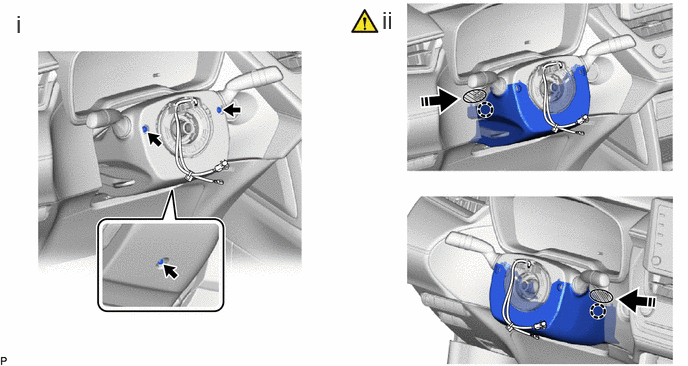
2.REMOVE LOWER STEERING COLUMN COVER
|
|
|

|
Push | 
|
Push Area |
Remove the 3 screws.
While pressing the push area shown in the illustration to disengage the claws, slightly lower the lower steering column cover.
45286B
3.REMOVE UPPER STEERING COLUMN COVER
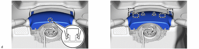
89782
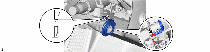
4.REMOVE TRANSPONDER KEY COIL (w/o Smart Entry and Start System)
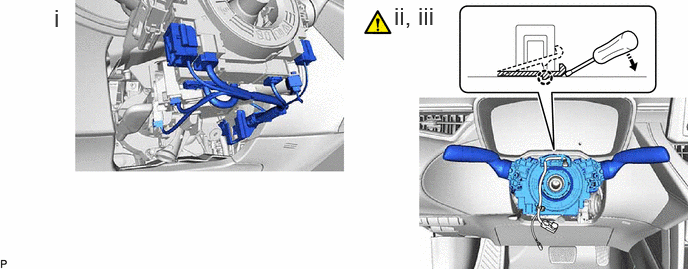
5.REMOVE TURN SIGNAL SWITCH ASSEMBLY WITH SPIRAL CABLE SUB-ASSEMBLY
|
|
|
|
|
Down | - | - |
Disconnect each connector.
- HINT:
-
As the illustration shown is an example, the actual details may differ.
Using pliers, expand the clamp.
While holding the clamp expanded, raise the claw using a screwdriver to disengage it, and then remove the turn signal switch assembly with spiral cable sub-assembly from the steering column assembly.
73900
6.REMOVE LOWER NO. 1 INSTRUMENT PANEL AIRBAG ASSEMBLY
84345
7.REMOVE STOP LIGHT SWITCH MOUNTING ADJUSTER
45259A
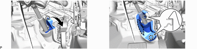
8.REMOVE COLUMN HOLE COVER SILENCER SHEET
|
|
Open | 
|
Place Hand Here |
45260
9.DISCONNECT NO. 2 STEERING INTERMEDIATE SHAFT ASSEMBLY

| *a | Matchmark | - | - |
Put matchmarks on the No. 2 steering intermediate shaft assembly and steering gear assembly.
Remove the bolt to disconnect the No. 2 steering intermediate shaft assembly from the steering gear assembly.
45260
10.REMOVE NO. 2 STEERING INTERMEDIATE SHAFT ASSEMBLY

| *a | Matchmark | - | - |
Put matchmarks on the No. 2 steering intermediate shaft assembly and steering column assembly.
Remove the bolt and No. 2 steering intermediate shaft assembly from the steering column assembly.
11.REMOVE STEERING COLUMN ASSEMBLY