STEERING GEAR / LINKAGE STEERING GEAR REMOVAL
CAUTION / NOTICE / HINT
The necessary procedures (adjustment, calibration, initialization, or registration) that must be performed after parts are removed and installed, or replaced during rack and pinion power steering gear assembly removal/installation are shown below.
| Replaced Part or Performed Procedure | Necessary Procedure | Effect/Inoperative Function when Necessary Procedure not Performed | Link |
|---|---|---|---|
|
*: Even when not replacing the part, it is necessary to perform the specified necessary procedures after installation. *1: Also necessary after performing a tire rotation. *2: It is not necessary to perform this procedure if the tire pressure warning valve and transmitters are installed to the same location. *3: The vehicle height changes because of suspension or tire replacement. |
|||
| Auxiliary battery terminal is disconnected/reconnected | Reset back door close position | Power Back Door System | ( 202111,999999,_59,_111831,_0505274,RM100000001ZMEG,) 202111,999999,_59,_111831,_0505274,RM100000001ZMEG,)
|
| Replacement of ECM | Update ECU security key | Vehicle Control History (RoB) are stored | (202111,999999,_V1,_111780,_0504977,RM100000001ZKRX,)
|
| Perform Vehicle Identification Number (VIN) or frame number registration | DTC is output | (202303,999999,_51,_111794,_0505179,RM1000000029YNJ,)
|
|
| Perform Total Short Trip Estimate Registration | - | ||
·
Replacement of engine assembly ·
Gas leak from exhaust system is repaired |
Inspection after repair | ·
Poor idle, etc. ·
Engine start function, etc. |
(202303,999999,_51,_111794,_0505179,RM1000000029YT1,)
|
| Replacement of inverter with converter assembly | Resolver learning | ·
DTCs are stored ·
Slight vibration at a vehicle speed of 5 km/h (3 mph) or less ·
Shock or vibration during acceleration |
for 2WD:(202111,999999,_51,_111804,_0508964,RM10000000202SL,)
for AWD:( 202111,999999,_51,_111804,_0501633,RM100000001Z6Y2,)
|
| Replacement of hybrid vehicle transaxle assembly | ·
Resolver learning ·
Initialize resolver |
||
| Replacement of front bumper assembly* | Front television camera view adjustment | Panoramic View Monitor System | (202409,999999,_56,_111825,_0500432,RM100000002O1F6,)
|
| Front wheel alignment adjustment | Perform "Calibration" | ·
DTCs are stored ·
ABS warning light illuminates ·
Brake system warning light (yellow indicator) illuminates ·
Slip indicator light illuminates ·
Electronically controlled brake system does not operate correctly |
(202203,999999,_54,_111814,_0500722,RM1000000022HHI,)
|
| Tires | ·
Initialization*1*2 ·
Tire Position Identification*1*2 |
Tire Pressure Warning System | Refer to Procedures Necessary When Replacing Parts (for Tire Pressure Warning System)
( 202409,999999,_V1,_111780,_0504977,RM100000002OMBP,)
|
| Suspension parts*3 | Parking assist ECU initialization | Panoramic View Monitor System | (202409,999999,_56,_111825,_0500432,RM100000002O1F6,)
|
| Rear television camera assembly optical axis (Back camera position setting) | Parking Assist Monitor System | (202409,999999,_56,_111825,_0524148,RM100000002OUWG,)
|
|
| Rack and pinion power steering gear assembly | Update ECU security key | Vehicle Control History (RoB) are stored | (202111,999999,_V1,_111780,_0504977,RM100000001ZKRX,)
|
| ECU configuration | ·
Vehicle Control History (RoB) are stored ·
EPS warning light illuminates |
(202111,999999,_V1,_111780,_0504977,RM100000001ZKRW,)
|
|
| Power steering ECU initial setting | ·
Vehicle Control History (RoB) are stored ·
EPS warning light illuminates |
(202111,999999,_55,_111821,_0503296,RM100000001ZE3A,)
|
|
- CAUTION:
- ·
 2.219,0.813 2.646,0.813 false 2.698,0.729 3.01,0.927 0.313,0.198 10 false *a
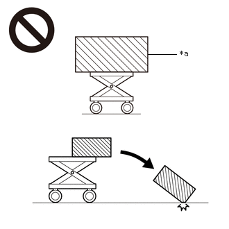
*a An Object Exceeding Weight Limit of Engine Lifter
The engine assembly with transaxle is very heavy. Be sure to follow the procedure described in the repair manual, or the engine lifter may suddenly drop or the engine assembly with transaxle may fall off the engine lifter.
·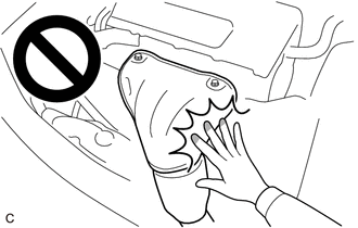
To prevent burns, do not touch the engine, exhaust manifold or other high temperature components while the engine is hot.
- HINT:
-
When the cable is disconnected / reconnected to the auxiliary battery terminal, systems temporarily stop operating. However, each system has a function that completes learning the first time the system is used.
Items for which learning is completed by driving the vehicle Effect/Inoperative Function when Necessary Procedure not Performed Necessary Procedure Link Lane Tracing Assist System Drive the vehicle straight ahead at 35 km/h (22 mph) or more for 5 seconds or more. ( 202111,999999,_95,_111850,_0502173,RM100000001Z92I,)
Pre-collision System
Items for which learning is completed by operating the vehicle normally Effect/Inoperative Function when Necessary Procedure not Performed Necessary Procedure Link Power Door Lock Control System
·Back door opener
Perform door unlock operation with door control switch or electrical key transmitter sub-assembly switch. ( 202111,999999,_58,_111830,_0505351,RM100000001ZMT3,)
Air Conditioning System After the ignition switch is turned to ON, the servo motor standard position is recognized. -
| Replaced Part or Performed Procedure | Necessary Procedure | Effect/Inoperative Function when Necessary Procedure not Performed | Link |
|---|---|---|---|
|
*: Even when not replacing the part, it is necessary to perform the specified necessary procedures after installation. *1: Also necessary after performing a tire rotation. *2: It is not necessary to perform this procedure if the tire pressure warning valve and transmitters are installed to the same location. *3: If the vehicle height has changed due to suspension or tire replacement. *4: When the starter assembly is replaced, "ST relay" must be also replaced. *5: If transaxle compensation code read from ECM *6: If transaxle compensation code not read from ECM |
|||
| Battery terminal is disconnected/reconnected | Reset back door close position | Power Back Door System | (202111,999999,_59,_111831,_0505274,RM100000001ZMEG,)
|
| Replacement of ECM | Update ECU security key | Vehicle Control History (RoB) are stored | (202111,999999,_V1,_111780,_0504977,RM100000001ZKRX,)
|
| Perform Vehicle Identification Number (VIN) or frame number registration | DTC is output | (202303,999999,_51,_111785,_0504416,RM1000000029BFA,)
|
|
| Code registration | Engine start | See Service Bulletin for the registration method | |
·
Transfer transaxle compensation code*5 ·
Reset transaxle compensation code*6 ·
CVT oil pressure calibration ·
Perform road test to allow ECM to learn |
·
Large shift shock ·
Deterioration of fuel efficiency |
Initialization:(202303,999999,_52,_111806,_0584611,RM1000000029R1M,)
Registration:( 202303,999999,_52,_111806,_0584611,RM1000000029R1L,)
|
|
·
Replacement of engine assembly ·
Gas leak from exhaust system is repaired |
Inspection after repair | ·
Poor idle, etc. ·
Engine start function, etc. |
(202303,999999,_51,_111785,_0504416,RM1000000029BFF,)
|
| Replacement of Starter assembly*4 | Clear the number of starter operations | Stop and Start System | (202111,999999,_51,_111803,_0509671,RM1000000020651,)
|
| Replacement of Battery | Integrated current value initialization | ||
·
Replacement of Continuously variable transaxle assembly ·
Replacement of CVT Fluid |
Air bleed the oil pump with motor assembly | ||
| Replacement of continuously variable transaxle assembly | ·
Input transaxle compensation code into ECM ·
Perform reset memory ·
CVT oil pressure calibration ·
Perform road test to allow ECM to learn |
·
Large shift shock ·
Deterioration of fuel efficiency |
Initialization:(202303,999999,_52,_111806,_0584611,RM1000000029R1M,)
Registration:( 202303,999999,_52,_111806,_0584611,RM1000000029R1L,)
|
| Replacement of CVT fluid | ATF thermal degradation estimate reset | The value of the Data List item "ATF Thermal Degradation Estimate" is not estimated correctly | (202303,999999,_52,_111806,_0584611,RM1000000029R1M,)
|
| Front wheel alignment adjustment | ·
Perform reset memory ·
Perform "Calibration" |
·
DTCs are stored ·
ABS warning light illuminates ·
Slip indicator light illuminates ·
Electronically controlled brake system does not operate correctly |
(202203,999999,_54,_111814,_0500728,RM1000000022HI0,)
|
| Front bumper assembly* | Front television camera view adjustment | Panoramic View Monitor System | (202409,999999,_56,_111825,_0500432,RM100000002O1F6,)
|
| Tires | ·
Initialization*1*2 ·
Tire Position Identification*1*2 |
Tire Pressure Warning System | Refer to Procedures Necessary When Replacing Parts (for Tire Pressure Warning System)
( 202409,999999,_V1,_111780,_0504977,RM100000002OMBP,)
|
| Suspension parts*3 | Parking assist ECU initialization | Panoramic View Monitor System | (202409,999999,_56,_111825,_0500432,RM100000002O1F6,)
|
| Rear television camera assembly optical axis (Back camera position setting) | Parking Assist Monitor System | (202409,999999,_56,_111825,_0524148,RM100000002OUWG,)
|
|
| Rack and pinion power steering gear assembly | Update ECU security key | Vehicle Control History (RoB) are stored | (202111,999999,_V1,_111780,_0504977,RM100000001ZKRX,)
|
| ECU configuration | ·
Vehicle Control History (RoB) are stored ·
EPS warning light illuminates |
(202111,999999,_V1,_111780,_0504977,RM100000001ZKRW,)
|
|
| Power steering ECU initial setting | ·
Vehicle Control History (RoB) are stored ·
EPS warning light illuminates |
(202111,999999,_55,_111821,_0503296,RM100000001ZE3A,)
|
|
- CAUTION:
- ·
2.219,0.813 2.646,0.813 false 2.698,0.729 3.01,0.927 0.313,0.198 10 false *a
*a An Object Exceeding Weight Limit of Engine Lifter
The engine assembly with transaxle is very heavy. Be sure to follow the procedure described in the repair manual, or the engine lifter may suddenly drop or the engine assembly with transaxle may fall off the engine lifter.
·
To prevent burns, do not touch the engine, exhaust manifold or other high temperature components while the engine is hot.
- HINT:
-
When the cable is disconnected / reconnected to the battery terminal, systems temporarily stop operating. However, each system has a function that completes learning the first time the system is used.
Items for which learning is completed by driving the vehicle Effect/Inoperative Function when Necessary Procedure not Performed Necessary Procedure Link Lane Tracing Assist System Drive the vehicle straight ahead at 15 km/h (10 mph) or more for 1 seconds or more. ( 202111,999999,_95,_111850,_0502173,RM100000001Z92I,)
Pre-collision System Stop and Start System Idle the engine for approximately 5 to 60 minutes or drive the vehicle until stop and start control is permitted ( 202406,999999,_51,_111803,_0509671,RM100000002KOGF,)
Items for which learning is completed by operating the vehicle normally Effect/Inoperative Function when Necessary Procedure not Performed Necessary Procedure Link Power Door Lock Control System
·Back door opener
Perform door unlock operation with door control switch or electrical key transmitter sub-assembly switch. ( 202111,999999,_58,_111830,_0505351,RM100000001ZMT3,)
Air Conditioning System After the ignition switch is turned to ON, the servo motor standard position is recognized. -
PROCEDURE

 1. PRECAUTION
2. ALIGN FRONT WHEELS FACING STRAIGHT AHEAD
3. SECURE STEERING WHEEL
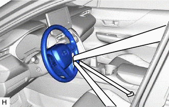
Secure the steering wheel with the seat belt in order to prevent rotation.
- HINT:
-
This operation is useful to prevent damage to the spiral cable.
4.REMOVE FRONT WHEELS
45220
5.SEPARATE STEERING INTERMEDIATE SHAFT ASSEMBLY
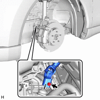
| *a | Matchmark |
Remove the bolt and slide the steering intermediate shaft assembly.
- NOTICE:
-
Do not separate the steering intermediate shaft assembly from the rack and pinion power steering gear assembly.
Put matchmarks on the rack and pinion power steering gear assembly and steering intermediate shaft assembly.
Separate the steering intermediate shaft assembly from the rack and pinion power steering gear assembly.
45470
6.SEPARATE TIE ROD ASSEMBLY LH
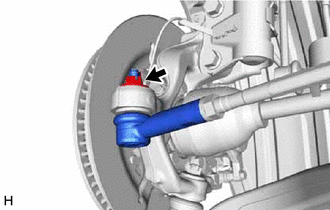
Remove the cotter pin and nut.
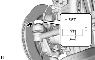
Install SST to the tie rod assembly LH as shown in the illustration.
- SST
- 09960-20010 (09961-02060)
- NOTICE:
-
Make sure that the upper ends of the tie rod assembly LH and SST are aligned.
for 2WD:
Using SST, separate the tie rod assembly LH from the steering knuckle LH as shown in the illustration.
- SST
- 09960-20010 (09961-02010)
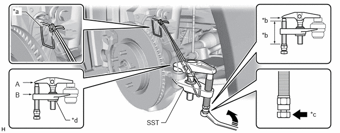
| *a | String | *b | Molybdenum Grease Application Area |
| *c | Place wrench here | *d | Center Nut |

|
Turn | - | - |
- CAUTION:
-
Apply molybdenum grease to the threads and end of the SST bolt.
- NOTICE:
- ·
Be sure to tighten the string firmly to secure SST to the steering knuckle LH to prevent SST from falling off.
·Install SST with the center nut so that (A) and (B) shown in the illustration are parallel. Otherwise, the ball joint dust cover may be damaged.
·Be sure to place the wrench on the part shown in the illustration.
·Do not damage the front disc brake dust cover.
·Do not damage the ball joint dust cover.
·Do not damage the steering knuckle LH.
for AWD:
Using SST, separate the tie rod assembly LH from the steering knuckle LH as shown in the illustration.
- SST
- 09960-20010 (09961-02010)
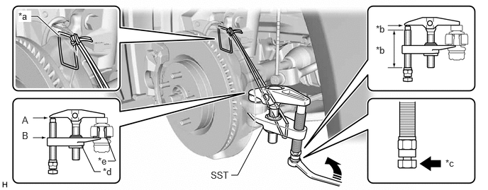
| *a | String | *b | Molybdenum Grease Application Area |
| *c | Place wrench here | *d | Center Nut |
| *e | Spacer | - | - |
|
|
Turn | - | - |
- CAUTION:
-
Apply molybdenum grease to the threads and end of the SST bolt.
- NOTICE:
- ·
Be sure to tighten the string firmly to secure SST to the steering knuckle LH to prevent SST from falling off.
·Install SST with the center nut so that (A) and (B) shown in the illustration are parallel. Otherwise, the ball joint dust cover may be damaged.
·Be sure to place the wrench on the part shown in the illustration.
·Do not damage the front disc brake dust cover.
·Do not damage the ball joint dust cover.
·Do not damage the steering knuckle LH.
·Make sure that SST is securely positioned on the spacer.
·If the steering knuckle spacer has come off, replace the steering knuckle with a new one.
45460
7.SEPARATE TIE ROD ASSEMBLY RH
- HINT:
-
Perform the same procedure as for the LH side.
8.REMOVE ENGINE ASSEMBLY WITH TRANSAXLE
for M20C-FKS, M20D-FKS: Click hereEngine / Hybrid System>M20C-FKS, M20D-FKS (ENGINE MECHANICAL)>ENGINE ASSEMBLY>REMOVAL202409,999999,_51,_111786,_0499722,RM100000002OLFC,
for A25D-FXS, A25F-FXS: Click hereEngine / Hybrid System>A25D-FXS, A25F-FXS (ENGINE MECHANICAL)>ENGINE ASSEMBLY>REMOVAL202409,999999,_51,_111795,_0503439,RM100000002OMZA,
45319
9.REMOVE STEERING GEAR HEAT INSULATOR
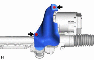
Remove the 2 bolts and steering gear heat insulator from the rack and pinion power steering gear assembly.
10.DISCONNECT WIRE HARNESS
Disconnect the wire harness connector from the rack and pinion power steering gear assembly.
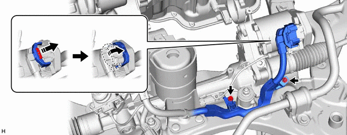
- HINT:
-
Release the lock before rotating the lock lever.
Remove the 2 bolts and separate the wire harness from the rack and pinion power steering gear assembly.
23825A
11.REMOVE FUEL DELIVERY GUARD
for M20C-FKS, M20D-FKS: Click hereEngine / Hybrid System>M20C-FKS, M20D-FKS (ENGINE MECHANICAL)>ENGINE ASSEMBLY>REMOVAL202409,999999,_51,_111786,_0499722,RM100000002OLFC_01_0292,
for A25D-FXS, A25F-FXS: Click hereEngine / Hybrid System>A25D-FXS, A25F-FXS (ENGINE MECHANICAL)>ENGINE ASSEMBLY>REMOVAL202409,999999,_51,_111795,_0503439,RM100000002OMZA_01_0292,
12.INSTALL ENGINE HANGERS
for M20C-FKS, M20D-FKS: Click hereEngine / Hybrid System>M20C-FKS, M20D-FKS (ENGINE MECHANICAL)>ENGINE ASSEMBLY>REMOVAL202409,999999,_51,_111786,_0499722,RM100000002OLFC_01_0270,
for A25D-FXS, A25F-FXS: Click hereEngine / Hybrid System>A25D-FXS, A25F-FXS (ENGINE MECHANICAL)>ENGINE ASSEMBLY>REMOVAL202409,999999,_51,_111795,_0503439,RM100000002OMZA_01_0270,
13.REMOVE FRONT FRAME ASSEMBLY
14.REMOVE FRONT STABILIZER BAR WITH BRACKET
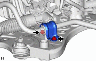
Remove the 2 bolts and separate the front No. 1 stabilizer bracket LH from the front frame assembly.
Remove the 2 bolts and separate the front No. 1 stabilizer bracket RH from the front frame assembly.
- HINT:
-
Perform the same procedure as for the LH side.
Remove the front stabilizer bar with the 2 front stabilizer links, front No. 1 stabilizer bracket LH, front No. 1 stabilizer bracket RH and 2 front No. 1 stabilizer bar bushings from the front frame assembly.
44250
15.REMOVE RACK AND PINION POWER STEERING GEAR ASSEMBLY
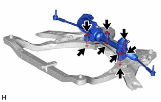
Remove the 4 bolts, 4 nuts and rack and pinion power steering gear assembly from the front frame assembly.
- NOTICE:
-
Because the nut has its own stopper, do not turn the nut. Loosen the bolt with the nut secured.
44250
16.SECURE RACK AND PINION POWER STEERING GEAR ASSEMBLY
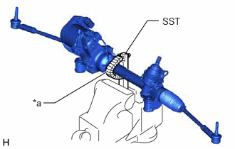
| *a | Protective Tape |
Using SST, secure the rack and pinion power steering gear assembly in a vise.
- SST
- 09612-00012
- HINT:
-
Wrap SST with protective tape before use.
45470
17.REMOVE TIE ROD ASSEMBLY LH
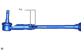
| *a | Matchmark |
Put matchmarks on the tie rod assembly LH and rack and pinion power steering gear assembly.
Remove the tie rod assembly LH and lock nut.
45460
18.REMOVE TIE ROD ASSEMBLY RH
- HINT:
-
Perform the same procedure as for the LH side.