PARK ASSIST / MONITORING PANORAMIC VIEW MONITOR SYSTEM C168811 Camera Power Supply Circuit Short to Ground C168812 Camera Power Supply Circuit Short to Battery
DESCRIPTION
This DTC is output when the self diagnostic function of the parking assist ECU detects an abnormal value of the power supply voltage supplied to the rear/front/side camera LH/side camera RH.
| DTC No. | Detection Item | DTC Detection Condition | Trouble Area | DTC Output from | Priority |
|---|---|---|---|---|---|
| C168811 | Camera Power Supply Circuit Short to Ground | Camera power supply voltage value abnormal (less than lower limit) | ·
Harness or connector ·
Parking assist ECU ·
Front television camera assembly ·
Rear television camera assembly ·
Side television camera assembly LH ·
Side television camera assembly RH |
Circumference Monitoring Camera Control Module | A |
| C168812 | Camera Power Supply Circuit Short to Battery | Camera power supply voltage value abnormal (higher than upper limit) | ·
Harness or connector ·
Parking assist ECU ·
Front television camera assembly ·
Rear television camera assembly ·
Side television camera assembly LH ·
Side television camera assembly RH |
Circumference Monitoring Camera Control Module | A |
WIRING DIAGRAM
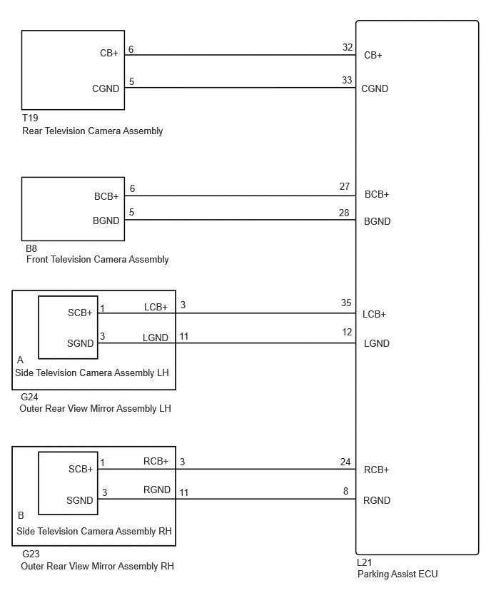
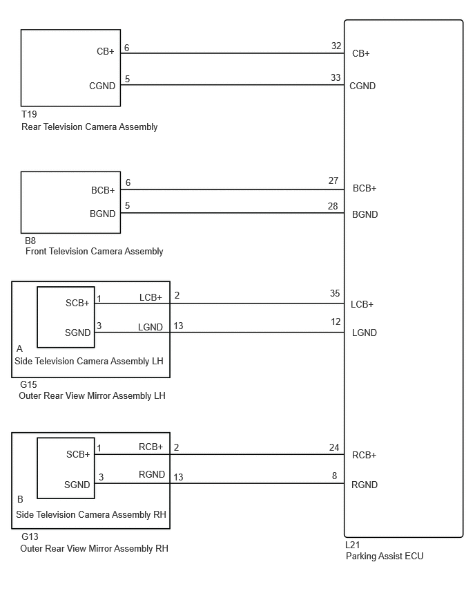
CAUTION / NOTICE / HINT
- NOTICE:
-
Depending on the parts that are replaced or operations that are performed during vehicle inspection or maintenance, calibration of other systems as well as the panoramic view monitor system may be needed.
PROCEDURE
Choose the model to be inspected.
- Result:
Result Proceed to w/o Seat Position Memory A w/ Seat Position Memory B
A
B
Disconnect the L21 parking assist ECU connector.
Disconnect the T19 rear television camera assembly connector.
Measure the resistance according to the value(s) in the table below.
- Standard Resistance:
Tester Connection Condition Specified Condition Click Location & Routing(L21,T19)Location & Routingewd_type=routing;type=c,c;code=L21,T19
Click Connector(L21)Instrument Panel>No. 2 Floor Wire>Parking Assist ECUewd_type=component;type=c;code=L21;pinno=32,33
Click Connector(T19)Body>No. 1 Back Door Wire>Rear Television Camera Assemblyewd_type=component;type=c;code=T19;pinno=6,5
L21-32 (CB+) - T19-6 (CB+) Always Below 1 Ω L21-33 (CGND) - T19-5 (CGND) Always Below 1 Ω L21-32 (CB+) or T19-6 (CB+) - Body ground Always 10 kΩ or higher L21-33 (CGND) or T19-5 (CGND) - Body ground Always 10 kΩ or higher
- Result:
Proceed to OK NG
OK
NG
Disconnect the L21 parking assist ECU connector.
Disconnect the B8 front television camera assembly connector.
Measure the resistance according to the value(s) in the table below.
- Standard Resistance:
Tester Connection Condition Specified Condition Click Location & Routing(L21,B8)Location & Routingewd_type=routing;type=c,c;code=L21,B8
Click Connector(L21)Instrument Panel>No. 2 Floor Wire>Parking Assist ECUewd_type=component;type=c;code=L21;pinno=27,28
L21-27 (BCB+) - B8-6 (BCB+) Always Below 1 Ω L21-28 (BGND) - B8-5 (BGND) Always Below 1 Ω L21-27 (BCB+) or B8-6 (BCB+) - Body ground Always 10 kΩ or higher L21-28 (BGND) or B8-5 (BGND) - Body ground Always 10 kΩ or higher
- Result:
Proceed to OK NG
OK
NG
Disconnect the L21 parking assist ECU connector.
Disconnect the G23 outer rear view mirror assembly RH connector.
Measure the resistance according to the value(s) in the table below.
- Standard Resistance:
Tester Connection Condition Specified Condition Click Location & Routing(L21,G23)Location & Routingewd_type=routing;type=c,c;code=L21,G23
Click Connector(L21)Instrument Panel>No. 2 Floor Wire>Parking Assist ECUewd_type=component;type=c;code=L21;pinno=24,8
Click Connector(G23)Body>Front Door Wire RH / Front Door Wire LH>Outer Rear View Mirror Assembly RHewd_type=component;type=c;code=G23;pinno=3,11
L21-24 (RCB+) - G23-3 (RCB+) Always Below 1 Ω L21-8 (RGND) - G23-11 (RGND) Always Below 1 Ω L21-24 (RCB+) or G23-3 (RCB+) - Body ground Always 10 kΩ or higher L21-8 (RGND) or G23-11 (RGND) - Body ground Always 10 kΩ or higher
- Result:
Proceed to OK NG
OK
NG
Disconnect the L21 parking assist ECU connector.
Disconnect the G24 outer rear view mirror assembly LH connector.
Measure the resistance according to the value(s) in the table below.
- Standard Resistance:
Tester Connection Condition Specified Condition Click Location & Routing(L21,G24)Location & Routingewd_type=routing;type=c,c;code=L21,G24
Click Connector(L21)Instrument Panel>No. 2 Floor Wire>Parking Assist ECUewd_type=component;type=c;code=L21;pinno=35,12
Click Connector(G24)Body>Front Door Wire RH / Front Door Wire LH>Outer Rear View Mirror Assembly LHewd_type=component;type=c;code=G24;pinno=3,11
L21-35 (LCB+) - G24-3 (LCB+) Always Below 1 Ω L21-12 (LGND) - G24-11 (LGND) Always Below 1 Ω L21-35 (LCB+) or G24-3 (LCB+) - Body ground Always 10 kΩ or higher L21-12 (LGND) or G24-11 (LGND) - Body ground Always 10 kΩ or higher
- Result:
Proceed to OK NG
OK
NG
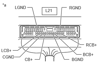
| *a | Component with harness connected
(Parking Assist ECU) |
Measure the resistance according to the value(s) in the table below.
- Standard Resistance:
Tester Connection Condition Specified Condition Click Location & Routing(L21)Location & Routingewd_type=routing;type=c;code=L21
Click Connector(L21)Instrument Panel>No. 2 Floor Wire>Parking Assist ECUewd_type=component;type=c;code=L21;pinno=33,28,12,8
L21-33 (CGND) - Body ground Always Below 1 Ω L21-28 (BGND) - Body ground Always Below 1 Ω L21-12 (LGND) - Body ground Always Below 1 Ω L21-8 (RGND) - Body ground Always Below 1 Ω
Measure the voltage according to the value(s) in the table below.
- Standard Voltage:
Tester Connection Switch Condition Specified Condition Click Location & Routing(L21)Location & Routingewd_type=routing;type=c;code=L21
Click Connector(L21)Instrument Panel>No. 2 Floor Wire>Parking Assist ECUewd_type=component;type=c;code=L21;pinno=32,33,27,28,35,12,24,8
L21-32 (CB+) - L21-33 (CGND) Ignition switch ON 5.5 to 7.05 V L21-27 (BCB+) - L21-28 (BGND) Ignition switch ON 5.5 to 7.05 V L21-35 (LCB+) - L21-12 (LGND) Ignition switch ON 5.5 to 7.05 V L21-24 (RCB+) - L21-8 (RGND) Ignition switch ON 5.5 to 7.05 V
- Result:
Proceed to OK NG
OK
NG
Disconnect the B8 front television camera assembly connector.
Disconnect the G23 outer rear view mirror assembly RH connector.
Disconnect the G24 outer rear view mirror assembly LH connector.
Clear the DTCs.
- Chassis > Circumference Monitoring Camera Control Module > Clear DTCs
- 50002 470
Check for DTCs.
- Chassis > Circumference Monitoring Camera Control Module > Trouble Codes
- 50001 470
- Result:
Result Proceed to Rear view screen is displayed, DTC C168811 or C168812 is not output A Rear view screen shows black, DTC C168811 or C168812 is output B
A
B
Disconnect the G23 outer rear view mirror assembly RH connector.
Disconnect the G24 outer rear view mirror assembly LH connector.
Clear the DTCs.
- Chassis > Circumference Monitoring Camera Control Module > Clear DTCs
- 50002 470
Check for DTCs.
- Chassis > Circumference Monitoring Camera Control Module > Trouble Codes
- 50001 470
- Result:
Result Proceed to Front view screen is displayed, DTC C168811 or C168812 is not output A Front view screen shows black, DTC C168811or C168812 is output B
A
B
Disconnect the G24 outer rear view mirror assembly LH connector.
Clear the DTCs.
- Chassis > Circumference Monitoring Camera Control Module > Clear DTCs
- 50002 470
Check for DTCs.
- Chassis > Circumference Monitoring Camera Control Module > Trouble Codes
- 50001 470
- Result:
Result Proceed to Right side of side view screen is displayed, DTC C168811 or C168812 is not output A Right side of side view screen shows black, DTC C168811 or C168812 is output B
A
B
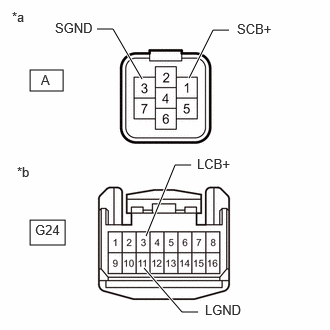
| *a | Front view of wire harness connector
(to Side Television Camera Assembly LH) |
| *b | Front view of wire harness connector
(to Outer Rear View Mirror Assembly LH) |
Disconnect the outer rear view mirror assembly LH connector.
Disconnect the side television camera assembly LH connector.
Measure the resistance according to the value(s) in the table below.
- Standard Resistance:
Tester Connection Condition Specified Condition Click Location & Routing(G24)Location & Routingewd_type=routing;type=c;code=G24
Click Connector(G24)Body>Front Door Wire RH / Front Door Wire LH>Outer Rear View Mirror Assembly LHewd_type=component;type=c;code=G24;pinno=3,11
A-1 (SCB+) - G24-3 (LCB+) Always Below 1 Ω A-3 (SGND) - G24-11 (LGND) Always Below 1 Ω
- Result:
Proceed to OK NG
OK
NG
Replace the side television camera assembly LH with a new or normally functioning one.
- Result:
Proceed to NEXT
NEXT
Clear the DTCs.
- Chassis > Circumference Monitoring Camera Control Module > Clear DTCs
- 50002 470
- Result:
Proceed to NEXT
NEXT
Check for DTCs.
- Chassis > Circumference Monitoring Camera Control Module > Trouble Codes
- 50001 470
- Result:
Result Proceed to C168811 or C168812 are not output A C168811 or C168812 is output B
A
B
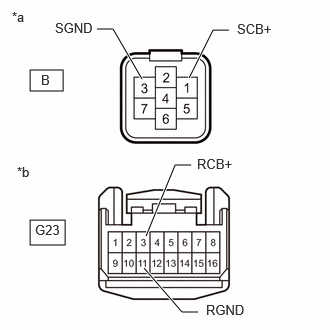
| *a | Front view of wire harness connector
(to Side Television Camera Assembly RH) |
| *b | Front view of wire harness connector
(to Outer Rear View Mirror Assembly RH) |
Disconnect the side television camera assembly RH connector.
Disconnect the outer rear view mirror assembly RH connector.
Measure the resistance according to the value(s) in the table below.
- Standard Resistance:
Tester Connection Condition Specified Condition Click Location & Routing(G23)Location & Routingewd_type=routing;type=c;code=G23
Click Connector(G23)Body>Front Door Wire RH / Front Door Wire LH>Outer Rear View Mirror Assembly RHewd_type=component;type=c;code=G23;pinno=3,11
B-1 (SCB+) - G23-3 (RCB+) Always Below 1 Ω B-3 (SGND) - G23-11 (RGND) Always Below 1 Ω
- Result:
Proceed to OK NG
OK
NG
Replace the side television camera assembly RH with a new or normally functioning one.
- Result:
Proceed to NEXT
NEXT
Clear the DTCs.
- Chassis > Circumference Monitoring Camera Control Module > Clear DTCs
- 50002 470
- Result:
Proceed to NEXT
NEXT
Check for DTCs.
- Chassis > Circumference Monitoring Camera Control Module > Trouble Codes
- 50001 470
- Result:
Result Proceed to C168811 or C168812 are not output A C168811/12 is output B
A
B
Disconnect the L21 parking assist ECU connector.
Disconnect the T19 rear television camera assembly connector.
Measure the resistance according to the value(s) in the table below.
- Standard Resistance:
Tester Connection Condition Specified Condition Click Location & Routing(L21,T19)Location & Routingewd_type=routing;type=c,c;code=L21,T19
Click Connector(L21)Instrument Panel>No. 2 Floor Wire>Parking Assist ECUewd_type=component;type=c;code=L21;pinno=32,33
Click Connector(T19)Body>No. 1 Back Door Wire>Rear Television Camera Assemblyewd_type=component;type=c;code=T19;pinno=6,5
L21-32 (CB+) - T19-6 (CB+) Always Below 1 Ω L21-33 (CGND) - T19-5 (CGND) Always Below 1 Ω L21-32 (CB+) or T19-6 (CB+) - Body ground Always 10 kΩ or higher L21-33 (CGND) or T19-5 (CGND) - Body ground Always 10 kΩ or higher
- Result:
Proceed to OK NG
OK
NG
Disconnect the L21 parking assist ECU connector.
Disconnect the B8 front television camera assembly connector.
Measure the resistance according to the value(s) in the table below.
- Standard Resistance:
Tester Connection Condition Specified Condition Click Location & Routing(L21,B8)Location & Routingewd_type=routing;type=c,c;code=L21,B8
Click Connector(L21)Instrument Panel>No. 2 Floor Wire>Parking Assist ECUewd_type=component;type=c;code=L21;pinno=27,28
L21-27 (BCB+) - B8-6 (BCB+) Always Below 1 Ω L21-28 (BGND) - B8-5 (BGND) Always Below 1 Ω L21-27 (BCB+) or B8-6 (BCB+) - Body ground Always 10 kΩ or higher L21-28 (BGND) or B8-5 (BGND) - Body ground Always 10 kΩ or higher
- Result:
Proceed to OK NG
OK
NG
Disconnect the L21 parking assist ECU connector.
Disconnect the G13 outer rear view mirror assembly RH connector.
Measure the resistance according to the value(s) in the table below.
- Standard Resistance:
Tester Connection Condition Specified Condition Click Location & Routing(L21,G13)Location & Routingewd_type=routing;type=c,c;code=L21,G13
Click Connector(L21)Instrument Panel>No. 2 Floor Wire>Parking Assist ECUewd_type=component;type=c;code=L21;pinno=24,8
Click Connector(G13)Body>Front Door Wire RH / Front Door Wire LH>Outer Rear View Mirror Assembly RHewd_type=component;type=c;code=G13;pinno=2,13
L21-24 (RCB+) - G13-2 (RCB+) Always Below 1 Ω L21-8 (RGND) - G13-13 (RGND) Always Below 1 Ω L21-24 (RCB+) or G13-2 (RCB+) - Body ground Always 10 kΩ or higher L21-8 (RGND) or G13-13 (RGND) - Body ground Always 10 kΩ or higher
- Result:
Proceed to OK NG
OK
NG
Disconnect the L21 parking assist ECU connector.
Disconnect the G15 outer rear view mirror assembly LH connector.
Measure the resistance according to the value(s) in the table below.
- Standard Resistance:
Tester Connection Condition Specified Condition Click Location & Routing(L21,G15)Location & Routingewd_type=routing;type=c,c;code=L21,G15
Click Connector(L21)Instrument Panel>No. 2 Floor Wire>Parking Assist ECUewd_type=component;type=c;code=L21;pinno=35,12
Click Connector(G15)Body>Front Door Wire RH / Front Door Wire LH>Outer Rear View Mirror Assembly LHewd_type=component;type=c;code=G15;pinno=2,13
L21-35 (LCB+) - G15-2 (LCB+) Always Below 1 Ω L21-12 (LGND) - G15-13 (LGND) Always Below 1 Ω L21-35 (LCB+) or G15-2 (LCB+) - Body ground Always 10 kΩ or higher L21-12 (LGND) or G15-13 (LGND) - Body ground Always 10 kΩ or higher
- Result:
Proceed to OK NG
OK
NG
| *a | Component with harness connected
(Parking Assist ECU) |
Measure the resistance according to the value(s) in the table below.
- Standard Resistance:
Tester Connection Condition Specified Condition Click Location & Routing(L21)Location & Routingewd_type=routing;type=c;code=L21
Click Connector(L21)Instrument Panel>No. 2 Floor Wire>Parking Assist ECUewd_type=component;type=c;code=L21;pinno=33,28,12,8
L21-33 (CGND) - Body ground Always Below 1 Ω L21-28 (BGND) - Body ground Always Below 1 Ω L21-12 (LGND) - Body ground Always Below 1 Ω L21-8 (RGND) - Body ground Always Below 1 Ω
Measure the voltage according to the value(s) in the table below.
- Standard Voltage:
Tester Connection Switch Condition Specified Condition Click Location & Routing(L21)Location & Routingewd_type=routing;type=c;code=L21
Click Connector(L21)Instrument Panel>No. 2 Floor Wire>Parking Assist ECUewd_type=component;type=c;code=L21;pinno=32,33,27,28,35,12,24,8
L21-32 (CB+) - L21-33 (CGND) Ignition switch ON 5.5 to 7.05 V L21-27 (BCB+) - L21-28 (BGND) Ignition switch ON 5.5 to 7.05 V L21-35 (LCB+) - L21-12 (LGND) Ignition switch ON 5.5 to 7.05 V L21-24 (RCB+) - L21-8 (RGND) Ignition switch ON 5.5 to 7.05 V
- Result:
Proceed to OK NG
OK
NG
Disconnect the B8 front television camera assembly connector.
Disconnect the G13 outer rear view mirror assembly RH connector.
Disconnect the G15 outer rear view mirror assembly LH connector.
Clear the DTCs.
- Chassis > Circumference Monitoring Camera Control Module > Clear DTCs
- 50002 470
Check for DTCs.
- Chassis > Circumference Monitoring Camera Control Module > Trouble Codes
- 50001 470
- Result:
Result Proceed to Rear view screen is displayed, DTC C168811 or C168812 is not output A Rear view screen shows black, DTC C168811 or C168812 is output B
A
B
Disconnect the G13 outer rear view mirror assembly RH connector.
Disconnect the G15 outer rear view mirror assembly LH connector.
Clear the DTCs.
- Chassis > Circumference Monitoring Camera Control Module > Clear DTCs
- 50002 470
Check for DTCs.
- Chassis > Circumference Monitoring Camera Control Module > Trouble Codes
- 50001 470
- Result:
Result Proceed to Front view screen is displayed, DTC C168811 or C168812 is not output A Front view screen shows black, DTC C168811or C168812 is output B
A
B
Disconnect the G15 outer rear view mirror assembly LH connector.
Clear the DTCs.
- Chassis > Circumference Monitoring Camera Control Module > Clear DTCs
- 50002 470
Check for DTCs.
- Chassis > Circumference Monitoring Camera Control Module > Trouble Codes
- 50001 470
- Result:
Result Proceed to Right side of side view screen is displayed, DTC C168811 or C168812 is not output A Right side of side view screen shows black, DTC C168811 or C168812 is output B
A
B
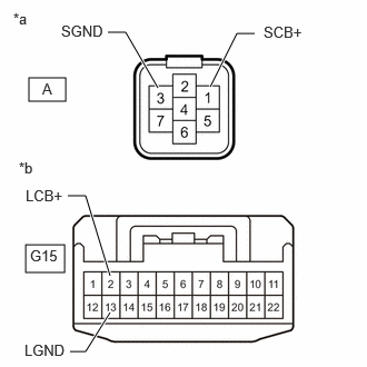
| *a | Front view of wire harness connector
(to Side Television Camera Assembly LH) |
| *b | Front view of wire harness connector
(to Outer Rear View Mirror Assembly LH) |
Disconnect the outer rear view mirror assembly LH connector.
Disconnect the side television camera assembly LH connector.
Measure the resistance according to the value(s) in the table below.
- Standard Resistance:
Tester Connection Condition Specified Condition Click Location & Routing(G15)Location & Routingewd_type=routing;type=c;code=G15
Click Connector(G15)Body>Front Door Wire RH / Front Door Wire LH>Outer Rear View Mirror Assembly LHewd_type=component;type=c;code=G15;pinno=2,13
A-1 (SCB+) - G15-2 (LCB+) Always Below 1 Ω A-3 (SGND) - G15-13 (LGND) Always Below 1 Ω
- Result:
Proceed to OK NG
OK
NG
Replace the side television camera assembly LH with a new or normally functioning one.
- Result:
Proceed to NEXT
NEXT
Clear the DTCs.
- Chassis > Circumference Monitoring Camera Control Module > Clear DTCs
- 50002 470
- Result:
Proceed to NEXT
NEXT
Check for DTCs.
- Chassis > Circumference Monitoring Camera Control Module > Trouble Codes
- 50001 470
- Result:
Result Proceed to C168811 or C168812 are not output A C168811 or C168812 is output B
A
B
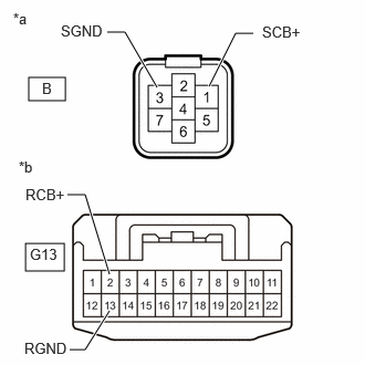
| *a | Front view of wire harness connector
(to Side Television Camera Assembly RH) |
| *b | Front view of wire harness connector
(to Outer Rear View Mirror Assembly RH) |
Disconnect the side television camera assembly RH connector.
Disconnect the outer rear view mirror assembly RH connector.
Measure the resistance according to the value(s) in the table below.
- Standard Resistance:
Tester Connection Condition Specified Condition Click Location & Routing(G13)Location & Routingewd_type=routing;type=c;code=G13
Click Connector(G13)Body>Front Door Wire RH / Front Door Wire LH>Outer Rear View Mirror Assembly RHewd_type=component;type=c;code=G13;pinno=2,13
B-1 (SCB+) - G13-2 (RCB+) Always Below 1 Ω B-3 (SGND) - G13-13 (RGND) Always Below 1 Ω
- Result:
Proceed to OK NG
OK
NG
Replace the side television camera assembly RH with a new or normally functioning one.
- Result:
Proceed to NEXT
NEXT
Clear the DTCs.
- Chassis > Circumference Monitoring Camera Control Module > Clear DTCs
- 50002 470
- Result:
Proceed to NEXT
NEXT
Check for DTCs.
- Chassis > Circumference Monitoring Camera Control Module > Trouble Codes
- 50001 470
- Result:
Result Proceed to C168811 or C168812 are not output A C168811/12 is output B
A
B