BRAKE CONTROL / DYNAMIC CONTROL SYSTEMS ELECTRONICALLY CONTROLLED BRAKE SYSTEM(for Gasoline Model (NR Series)) P057112 Brake Switch "A" Circuit Short to Battery
DESCRIPTION
The skid control ECU (brake actuator assembly) receives stop light switch assembly signals and uses them to determine whether or not the brakes are applied.
DTCs may be stored if either of the following occurs:
Stop light switch assembly stuck on malfunction.
The accelerator and brake pedals are depressed simultaneously.*
- HINT:
-
*: The skid control ECU (brake actuator assembly) may store this DTC upon judging that a stuck on malfunction has occurred when the accelerator pedal and brake pedal are depressed simultaneously. However, this does not indicate a malfunction.
| DTC No. | Detection Item | DTC Detection Condition | Trouble Area |
|---|---|---|---|
| P057112 | Brake Switch "A" Circuit Short to Battery | The vehicle speed is 10 km/h (6 mph) or more, the accelerator pedal is depressed, the master cylinder pressure is 0.5 MPa (5.1 kgf/cm2, 72.5 psi) or less, and the stop light switch assembly is on for 60 seconds or more. | ·
Stop light switch assembly ·
Stop light switch assembly installation ·
Wire harness or connector ·
Skid control ECU (brake actuator assembly) ·
ECM ·
Shift lock control ECU (shift lock control unit assembly) ·
Certification ECU (smart key ECU assembly) |
WIRING DIAGRAM
CAUTION / NOTICE / HINT
- NOTICE:
- ·
Inspect the fuses for circuits related to this system before performing the following procedure.
·After replacing the skid control ECU (brake actuator assembly), perform acceleration sensor zero point calibration and store system information memorization.
·Before replacing the certification ECU (smart key ECU assembly), refer to Service Bulletin.
·DTC precaution
Procedure to clear warning lights (When not clearing DTCs) Procedure 1.Repair or replacement.
2.Turn the ignition switch to ON.
3.Drive the vehicle and depress the brake pedal 2 or 3 times to clear the warning lights.
PROCEDURE
Check the brake pedal height and stop light switch assembly installation.
- OK:
The brake pedal height and stop light switch assembly installation are normal.
- Result:
Proceed to OK NG
OK
NG
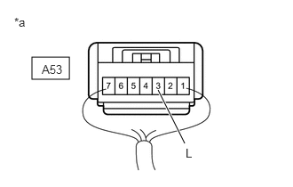
| *a | Component with harness connected
(Stop Light Switch Assembly) |
Make sure that there is no looseness at the locking part and the connecting part of the connector.
- OK:
The connector is securely connected.
Disconnect the A51 skid control ECU (brake actuator assembly) connector.
Check both the connector case and the terminals for deformation and corrosion.
- OK:
No deformation or corrosion.
Measure the voltage according to the value(s) in the table below.
- Standard Voltage:
Tester Connection Condition Specified Condition A53-3 (L) - Body ground Brake pedal released Below 1.5 V
- Result:
Proceed to OK NG
OK
NG
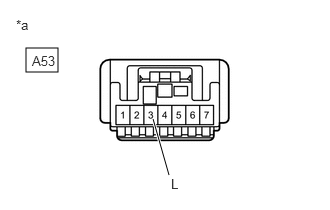
| *a | Front view of wire harness connector
(to Stop Light Switch Assembly) |
Make sure that there is no looseness at the locking part and the connecting part of the connector.
- OK:
The connector is securely connected.
Disconnect the A51 skid control ECU (brake actuator assembly) connector.
Disconnect the A53 stop light switch assembly connector.
Check both the connector case and the terminals for deformation and corrosion.
- OK:
No deformation or corrosion.
Measure the voltage according to the value(s) in the table below.
- Standard Voltage:
Tester Connection Condition Specified Condition A53-3 (L) - Body ground Always Below 1.5 V
- Result:
Proceed to OK NG
OK
NG
| *a | Front view of wire harness connector
(to Stop Light Switch Assembly) |
Make sure that there is no looseness at the locking part and the connecting part of the connector.
- OK:
The connector is securely connected.
Disconnect the A51 skid control ECU (brake actuator assembly) connector.
Disconnect the A53 stop light switch assembly connector.
Disconnect the A46 ECM connector.
Check both the connector case and the terminals for deformation and corrosion.
- OK:
No deformation or corrosion.
Measure the voltage according to the value(s) in the table below.
- Standard Voltage:
Tester Connection Condition Specified Condition A53-3 (L) - Body ground Always Below 1.5 V
- Result:
Proceed to OK NG
OK
NG
| *a | Front view of wire harness connector
(to Stop Light Switch Assembly) |
Make sure that there is no looseness at the locking part and the connecting part of the connector.
- OK:
The connector is securely connected.
Disconnect the A51 skid control ECU (brake actuator assembly) connector.
Disconnect the A53 stop light switch assembly connector.
Disconnect the A46 ECM connector.
Disconnect the I18 shift lock control ECU (shift lock control unit assembly) connector .
Check both the connector case and the terminals for deformation and corrosion.
- OK:
No deformation or corrosion.
Measure the voltage according to the value(s) in the table below.
- Standard Voltage:
Tester Connection Condition Specified Condition A53-3 (L) - Body ground Always Below 1.5 V
- Result:
Proceed to OK NG
OK
Click hereDrivetrain>K313 (CVT)>SHIFT LEVER>REMOVAL201906,999999,_52,_080728,_0392275,RM100000001HPBM,
NG
| *a | Front view of wire harness connector
(to Stop Light Switch Assembly) |
Make sure that there is no looseness at the locking part and the connecting part of the connector.
- OK:
The connector is securely connected.
Disconnect the A51 skid control ECU (brake actuator assembly) connector.
Disconnect the A53 stop light switch assembly connector.
Disconnect the A46 ECM connector.
Disconnect the I18 shift lock control ECU (shift lock control unit assembly) connector.
Disconnect the O61 certification ECU (smart key ECU assembly) connector.
Check both the connector case and the terminals for deformation and corrosion.
- OK:
No deformation or corrosion.
Measure the voltage according to the value(s) in the table below.
- Standard Voltage:
Tester Connection Condition Specified Condition A53-3 (L) - Body ground Always Below 1.5 V
- Result:
Proceed to OK NG
OK
NG