RM3660EC _58 Vehicle Interior _080793 METER / GAUGE / DISPLAY _0598151 METER / GAUGE SYSTEM(except 12.3 Inch Display) J

METER / GAUGE / DISPLAY  METER / GAUGE SYSTEM(except 12.3 Inch Display)  Steering Pad Switch Circuit  


DESCRIPTION

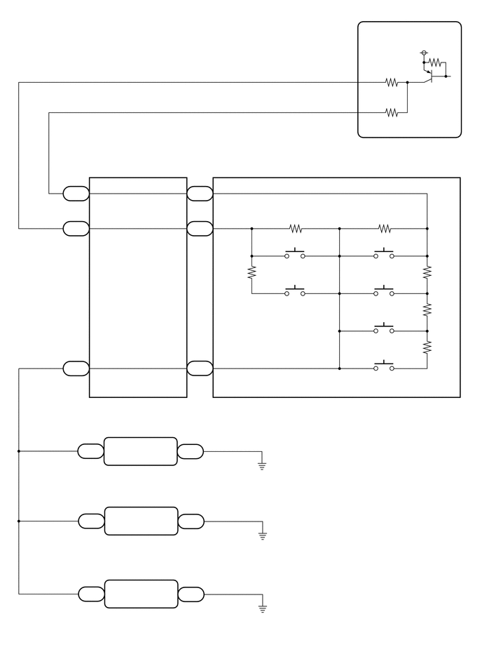
The combination meter assembly and steering pad switch assembly are connected via direct line. The multi-information display in the combination meter assembly is operated using the switches of the steering pad switch assembly.

WIRING DIAGRAM

except NR Series Engine
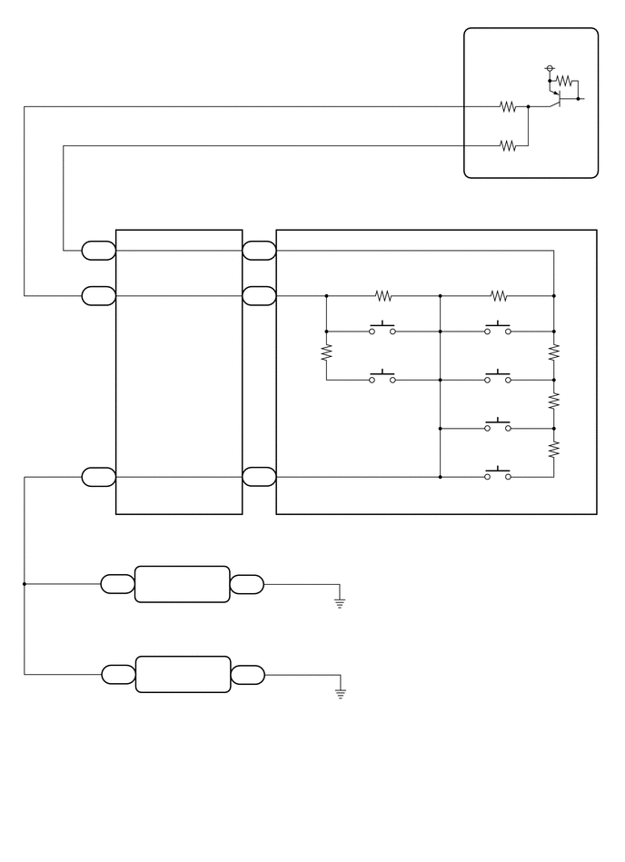

E459405
5.146,2.052 5.958,2.51 0.813,0.458 10 false I5 5.135,2.229 6.969,2.427 1.833,0.198 10 false Combination Meter Assembly 1.24,5.958 5.063,6.156 3.823,0.198 10 false Spiral Cable Sub-assembly 3.979,5.969 6.167,6.281 2.188,0.313 10 false Steering Pad Switch Assembly 2.719,6.625 3.094,6.833 0.375,0.208 10 false I210 0.979,6.979 3.51,7.198 2.531,0.219 10 false Radio and Display Receiver Assembly*1 5.365,1.031 5.75,1.24 0.385,0.208 10 false MSTI 5.375,1.427 5.844,1.625 0.469,0.198 10 false MSM+ 6.208,0.521 6.823,0.719 0.615,0.198 10 false 5 V 5.083,1.469 5.292,1.646 0.208,0.177 10 false 29 5.083,1.031 5.292,1.229 0.208,0.198 10 false 12 1.385,2.677 1.74,2.865 0.354,0.188 10 false +DP 1.385,3.198 1.813,3.396 0.427,0.198 10 false +DP2 1.031,2.792 1.333,2.979 0.302,0.188 10 false I82 2.927,2.594 3.083,2.771 0.156,0.177 10 false 4 2.927,3.115 3.094,3.302 0.167,0.188 10 false 5 1.094,5.188 1.708,5.385 0.615,0.198 10 false 4 2.885,5.188 3.5,5.385 0.615,0.198 10 false 10 1.052,2.583 1.26,2.781 0.208,0.198 10 false 11 1.042,3.104 1.26,3.302 0.219,0.198 10 false 10 4.302,3.865 4.917,4.063 0.615,0.198 10 false OK 5.552,3.885 6.167,4.083 0.615,0.198 10 false LEFT 4.177,4.438 4.792,4.635 0.615,0.198 10 false BACK 5.51,5.01 6.125,5.208 0.615,0.198 10 false DOWN 5.635,4.448 6.25,4.646 0.615,0.198 10 false UP 5.521,5.552 6.135,5.75 0.615,0.198 10 false RIGHT 1.271,6.406 1.885,6.604 0.615,0.198 10 false 20 2.781,6.406 3.396,6.604 0.615,0.198 10 false 1 1.594,6.604 1.969,6.792 0.375,0.188 10 false SWG 2.229,6.615 2.667,6.802 0.438,0.188 10 false GND1 1.385,5.271 1.844,5.469 0.458,0.198 10 false EAU 2.896,2.792 3.198,2.99 0.302,0.198 10 false z3 1.042,3.313 1.344,3.5 0.302,0.188 10 false I82 1.042,5.396 1.344,5.583 0.302,0.188 10 false I82 2.885,3.313 3.188,3.51 0.302,0.198 10 false z3 2.896,5.375 3.198,5.573 0.302,0.198 10 false z3 4.24,8.948 7.156,9.417 2.917,0.469 10 false *1: for Radio and Display Type 4.24,9.427 7.156,9.875 2.917,0.448 10 false *2: for Navigation Receiver Type 0.594,7.521 1.208,7.719 0.615,0.198 10 false *2 1.229,6.615 1.604,6.823 0.375,0.208 10 false I210 0.583,6.5 1.198,6.698 0.615,0.198 10 false *1 2.719,7.656 3.094,7.865 0.375,0.208 10 false I187 1.594,7.646 1.969,7.833 0.375,0.188 10 false SWG 2.24,7.646 2.677,7.833 0.438,0.188 10 false GND1 1.24,7.656 1.615,7.865 0.375,0.208 10 false I187 1.302,7.438 1.917,7.635 0.615,0.198 10 false 20 2.781,7.438 3.396,7.635 0.615,0.198 10 false 1 1.156,8 3.688,8.219 2.531,0.219 10 false Navigation Receiver Assembly*2


for NR Series Engine


E487843
6.198,0.552 6.688,0.781 0.49,0.229 10 false 5 V 5.375,0.99 5.865,1.219 0.49,0.229 10 false MSM+ 5.198,2.229 7.042,2.708 1.844,0.479 10 false Combination Meter Assembly 1.385,2.677 1.875,2.906 0.49,0.229 10 false +DP2 1.406,5.281 1.896,5.51 0.49,0.229 10 false EAU 1.26,5.969 3.031,6.281 1.771,0.313 10 false Spiral Cable Sub-assembly 4.281,3.854 4.771,4.083 0.49,0.229 10 false OK 4.198,4.406 4.688,4.635 0.49,0.229 10 false BACK 5.552,3.844 6.042,4.073 0.49,0.229 10 false LEFT 5.615,4.406 6.104,4.635 0.49,0.229 10 false UP 5.5,4.958 5.99,5.188 0.49,0.229 10 false DOWN 5.51,5.51 6,5.74 0.49,0.229 10 false RIGHT 4.052,5.99 6.073,6.333 2.021,0.344 10 false Steering Pad Switch Assembly 1.594,6.615 2.083,6.844 0.49,0.229 10 false SWG 2.24,6.615 2.729,6.844 0.49,0.229 10 false GND1 4.052,8.198 7.042,8.448 2.99,0.25 10 false *1: for Navigation Receiver Type (w/ RST Switch) 5.385,1.448 5.875,1.677 0.49,0.229 10 false MSTI 1.406,3.198 1.896,3.427 0.49,0.229 10 false +DP 4.063,9.198 7.104,9.729 3.042,0.531 10 false *3: for Radio and Display Type (except 10.25 Inch Display) 0.677,6.49 1.167,6.719 0.49,0.229 10 false *1 1.177,8.01 3.635,8.333 2.458,0.323 10 false Navigation Receiver Assembly*2 1.594,7.656 2.083,7.885 0.49,0.229 10 false SWG 2.229,7.656 2.719,7.885 0.49,0.229 10 false GND1 1.188,6.969 3.646,7.292 2.458,0.323 10 false Navigation Receiver Assembly*1 0.667,7.531 1.156,7.76 0.49,0.229 10 false *2 5.219,2.063 5.708,2.292 0.49,0.229 10 false I4 5.115,1.021 5.604,1.25 0.49,0.229 10 false 32 5.115,1.49 5.604,1.719 0.49,0.229 10 false 15 1.052,2.792 1.542,3.021 0.49,0.229 10 false I82 1.031,3.313 1.521,3.542 0.49,0.229 10 false I82 1.052,2.594 1.542,2.823 0.49,0.229 10 false 10 1.052,3.115 1.542,3.344 0.49,0.229 10 false 11 1.031,5.385 1.521,5.615 0.49,0.229 10 false I82 1.094,5.188 1.583,5.417 0.49,0.229 10 false 4 2.906,2.792 3.396,3.021 0.49,0.229 10 false z3 2.896,3.313 3.385,3.542 0.49,0.229 10 false z3 2.896,5.385 3.385,5.615 0.49,0.229 10 false z3 2.885,5.177 3.375,5.406 0.49,0.229 10 false 10 2.927,3.104 3.417,3.333 0.49,0.229 10 false 4 2.938,2.583 3.427,2.813 0.49,0.229 10 false 5 1.292,6.396 1.781,6.625 0.49,0.229 10 false 23 1.313,7.438 1.802,7.667 0.49,0.229 10 false 20 2.781,7.458 3.271,7.688 0.49,0.229 10 false 1 2.802,6.417 3.292,6.646 0.49,0.229 10 false 7 1.219,6.615 1.708,6.844 0.49,0.229 10 false I169 1.24,7.656 1.729,7.885 0.49,0.229 10 false I187 2.698,6.625 3.188,6.854 0.49,0.229 10 false I167 2.708,7.656 3.198,7.885 0.49,0.229 10 false I187 0.667,8.615 1.156,8.844 0.49,0.229 10 false *3 1.01,9.094 3.469,9.417 2.458,0.323 10 false Radio and Display Receiver Assembly*3 1.229,8.74 1.719,8.969 0.49,0.229 10 false I166 2.708,8.74 3.198,8.969 0.49,0.229 10 false I165 2.792,8.51 3.281,8.74 0.49,0.229 10 false 7 1.292,8.521 1.781,8.75 0.49,0.229 10 false 23 1.604,8.729 2.094,8.958 0.49,0.229 10 false SWG 2.24,8.729 2.729,8.958 0.49,0.229 10 false GND1 4.052,8.625 7.042,9.031 2.99,0.406 10 false *2: for Navigation Receiver Type (w/o RST Switch (except 10.25 Inch Display))


CAUTION / NOTICE / HINT

NOTICE:
·

When replacing the combination meter assembly, always replace it with a new one. If a combination meter assembly which was installed to another vehicle is used, the information stored in it will not match the information from the vehicle and a DTC may be stored.

·

except NR Series Engine

When replacing the combination meter assembly, update the ECU security key.

Click hereGeneral>SETUP>WHEN REPLACING OR REMOVING/INSTALLING PARTS>UPDATE ECU SECURITY KEY


PROCEDURE

1.PERFORM ACTIVE TEST USING GTS
a.

Perform the Active Test according to the display on the GTS.

Body Electrical > Combination Meter > Active Test
Tester Display Measurement Item Control Range Diagnostic Note
Multi Switch (Up) Performs the same operation as pressing the up switch on steering pad switch OFF or ON -
Multi Switch (Down) Performs the same operation as pressing the down switch on steering pad switch OFF or ON -
Multi Switch (Left) Performs the same operation as pressing the left switch on steering pad switch OFF or ON -
Multi Switch (Right) Performs the same operation as pressing the right switch on steering pad switch OFF or ON -
Multi Switch (Enter) Performs the same operation as pressing the OK switch on steering pad switch OFF or ON -
Multi Switch (Back) Performs the same operation as pressing the back switch on steering pad switch OFF or ON -
Body Electrical > Combination Meter > Active Test
Tester Display
Multi Switch (Up)
50004 409 316
Body Electrical > Combination Meter > Active Test
Tester Display
Multi Switch (Down)
50004 409 317
Body Electrical > Combination Meter > Active Test
Tester Display
Multi Switch (Left)
50004 409 318
Body Electrical > Combination Meter > Active Test
Tester Display
Multi Switch (Right)
50004 409 319
Body Electrical > Combination Meter > Active Test
Tester Display
Multi Switch (Enter)
50004 409 320
Body Electrical > Combination Meter > Active Test
Tester Display
Multi Switch (Back)
50004 409 321

Result:
Result Proceed to
Active Test can be performed correctly A
Active Test cannot be performed correctly B


A

2.READ VALUE USING GTS

B

2.READ VALUE USING GTS
a.

Read the Data List according to the display on the GTS.

Body Electrical > Combination Meter > Data List
Tester Display Measurement Item Range Normal Condition Diagnostic Note
Multi Switch (Up) Up switch on steering pad switch operation OFF or ON OFF: Switch released
ON: Switch pushed
-
Multi Switch (Down) Down switch on steering pad switch operation OFF or ON OFF: Switch released
ON: Switch pushed
-
Multi Switch (Left) Left switch on steering pad switch operation OFF or ON OFF: Switch released
ON: Switch pushed
-
Multi Switch (Right) Right switch on steering pad switch operation OFF or ON OFF: Switch released
ON: Switch pushed
-
Multi Switch (Enter) OK switch on steering pad switch operation OFF or ON OFF: Switch released
ON: Switch pushed
-
Multi Switch (Back) Back switch on steering pad switch operation OFF or ON OFF: Switch released
ON: Switch pushed
-
Body Electrical > Combination Meter > Data List
Tester Display
Multi Switch (Up)
Multi Switch (Down)
Multi Switch (Left)
Multi Switch (Right)
Multi Switch (Enter)
Multi Switch (Back)
50003 409 12,13,14,15,16,17

Result:
Result Proceed to
The value of the Data List item is correct, and the combination meter assembly operates correctly A
The value of the Data List item is correct, but the combination meter assembly does not operate correctly B
The Data List item changes correctly C


A

B

C

3.INSPECT STEERING PAD SWITCH ASSEMBLY

OK

4.INSPECT SPIRAL CABLE SUB-ASSEMBLY

NG

4.INSPECT SPIRAL CABLE SUB-ASSEMBLY

OK

5.CHECK COMBINATION METER ASSEMBLY (OUTPUT VOLTAGE)

NG

5.CHECK COMBINATION METER ASSEMBLY (OUTPUT VOLTAGE)
E383900C48
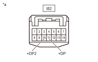
1.51,0.177 1.927,0.406 0.417,0.229 1.125,1.792 1.542,1.375 true 2.135,1.792 1.719,1.375 true 0.938,1.802 1.417,2.177 0.479,0.375 10 false +DP2 2.042,1.802 2.521,2.177 0.479,0.375 10 false +DP 0.094,0.073 0.573,0.448 0.479,0.375 10 false *a 1.625,0.219 2.031,0.417 0.406,0.198 10 false I82
*a Front view of wire harness connector
(to Spiral Cable Sub-assembly)


a.

Measure the voltage according to the value(s) in the table below.

Standard Voltage:
Tester Connection Condition Specified Condition
I82-11 (+DP) - Body ground Ignition switch ON 4.8 to 5.2 V
I82-10 (+DP2) - Body ground Ignition switch ON 4.8 to 5.2 V


Result:
Proceed to
OK
NG


OK

6.CONFIRM MODEL

NG

13.CONFIRM MODEL
6.CONFIRM MODEL
a.

Choose the model to be inspected.


Result:
Result Proceed to
except NR Series Engine A
for NR Series Engine B


A

7.CONFIRM MODEL

B

10.CONFIRM MODEL
7.CONFIRM MODEL
a.

Choose the model to be inspected.


Result:
Result Proceed to
for Radio and Display Type A
for Navigation Receiver Type B


A

8.CHECK HARNESS AND CONNECTOR (RADIO AND DISPLAY RECEIVER ASSEMBLY - SPIRAL CABLE SUB-ASSEMBLY AND BODY GROUND)

B

9.CHECK HARNESS AND CONNECTOR (NAVIGATION RECEIVER ASSEMBLY - SPIRAL CABLE SUB-ASSEMBLY AND BODY GROUND)
8.CHECK HARNESS AND CONNECTOR (RADIO AND DISPLAY RECEIVER ASSEMBLY - SPIRAL CABLE SUB-ASSEMBLY AND BODY GROUND)
a.

Disconnect the I210 radio and display receiver assembly connector.


b.

Measure the resistance according to the value(s) in the table below.

Standard Resistance:
Tester Connection Condition Specified Condition
I210-20 (SWG) - I82-4 (EAU) Always Below 1 Ω
I210-1 (GND1) - Body ground Always Below 1 Ω


Result:
Proceed to
OK
NG


OK

NG

REPAIR OR REPLACE HARNESS OR CONNECTOR

9.CHECK HARNESS AND CONNECTOR (NAVIGATION RECEIVER ASSEMBLY - SPIRAL CABLE SUB-ASSEMBLY AND BODY GROUND)
a.

Disconnect the I187 navigation receiver assembly connector.


b.

Measure the resistance according to the value(s) in the table below.

Standard Resistance:
Tester Connection Condition Specified Condition
I187-20 (SWG) - I82-4 (EAU) Always Below 1 Ω
I187-1 (GND1) - Body ground Always Below 1 Ω


Result:
Proceed to
OK
NG


OK

NG

REPAIR OR REPLACE HARNESS OR CONNECTOR

10.CONFIRM MODEL
a.

Choose the model to be inspected.


Result:
Result Proceed to
for Radio and Display Type A
for Navigation Receiver Type B


A

11.CHECK HARNESS AND CONNECTOR (RADIO AND DISPLAY RECEIVER ASSEMBLY - SPIRAL CABLE SUB-ASSEMBLY AND BODY GROUND)

B

12.CHECK HARNESS AND CONNECTOR (NAVIGATION RECEIVER ASSEMBLY - SPIRAL CABLE SUB-ASSEMBLY AND BODY GROUND)
11.CHECK HARNESS AND CONNECTOR (RADIO AND DISPLAY RECEIVER ASSEMBLY - SPIRAL CABLE SUB-ASSEMBLY AND BODY GROUND)
a.

Disconnect the I165 radio and display receiver assembly connector.


b.

Disconnect the I166 radio and display receiver assembly connector.


c.

Measure the resistance according to the value(s) in the table below.

Standard Resistance:
Tester Connection Condition Specified Condition
I166-23 (SWG) - I82-4 (EAU) Always Below 1 Ω
I165-7 (GND1) - Body ground Always Below 1 Ω


Result:
Proceed to
OK
NG


OK

NG

REPAIR OR REPLACE HARNESS OR CONNECTOR

12.CHECK HARNESS AND CONNECTOR (NAVIGATION RECEIVER ASSEMBLY - SPIRAL CABLE SUB-ASSEMBLY AND BODY GROUND)
a.

Disconnect the I169 or I167 navigation receiver assembly*1 connector.


b.

Disconnect the I187 navigation receiver assembly*2 connector.


c.

Measure the resistance according to the value(s) in the table below.

Standard Resistance:
Tester Connection Condition Specified Condition
I169-23 (SWG)*1 - I82-4 (EAU) Always Below 1 Ω
I187-20 (SWG)*2 - I82-4 (EAU) Always Below 1 Ω
I167-7 (GND1)*1 - Body ground Always Below 1 Ω
I187-1 (GND1)*2 - Body ground Always Below 1 Ω


*1: for Navigation Receiver Type (w/ RST Switch)

*2: for Navigation Receiver Type (w/o RST Switch (except 10.25 Inch Display))


Result:
Proceed to
OK
NG


OK

NG

REPAIR OR REPLACE HARNESS OR CONNECTOR

13.CONFIRM MODEL
a.

Choose the model to be inspected.


Result:
Result Proceed to
except NR Series Engine A
for NR Series Engine B


A

14.CHECK HARNESS AND CONNECTOR (SPIRAL CABLE SUB-ASSEMBLY - COMBINATION METER ASSEMBLY)

B

15.CHECK HARNESS AND CONNECTOR (SPIRAL CABLE SUB-ASSEMBLY - COMBINATION METER ASSEMBLY)
14.CHECK HARNESS AND CONNECTOR (SPIRAL CABLE SUB-ASSEMBLY - COMBINATION METER ASSEMBLY)
a.

Disconnect the I5 combination meter assembly connector.


b.

Measure the resistance according to the value(s) in the table below.

Standard Resistance:
Tester Connection Condition Specified Condition
I82-11 (+DP) - I5-29 (MSM+) Always Below 1 Ω
I82-10 (+DP2) - I5-12 (MSTI) Always Below 1 Ω
I82-11 (+DP) or I5-29 (MSM+) - Body ground Always 10 kΩ or higher
I82-10 (+DP2) or I5-12 (MSTI) - Body ground Always 10 kΩ or higher


Result:
Proceed to
OK
NG


OK

NG

REPAIR OR REPLACE HARNESS OR CONNECTOR

15.CHECK HARNESS AND CONNECTOR (SPIRAL CABLE SUB-ASSEMBLY - COMBINATION METER ASSEMBLY)
a.

Disconnect the I4 combination meter assembly connector.


b.

Measure the resistance according to the value(s) in the table below.

Standard Resistance:
Tester Connection Condition Specified Condition
I82-11 (+DP) - I4-32 (MSM+) Always Below 1 Ω
I82-10 (+DP2) - I4-15 (MSTI) Always Below 1 Ω
I82-11 (+DP) or I4-32 (MSM+) - Body ground Always 10 kΩ or higher
I82-10 (+DP2) or I4-15 (MSTI) - Body ground Always 10 kΩ or higher


Result:
Proceed to
OK
NG


OK

NG

REPAIR OR REPLACE HARNESS OR CONNECTOR