METER / GAUGE / DISPLAY COMBINATION METER REMOVAL
CAUTION / NOTICE / HINT
The necessary procedures (adjustment, calibration, initialization or registration) that must be performed after parts are removed and installed, or replaced during combination meter assembly removal/installation are shown below.
| Replaced Part or Performed Procedure | Necessary Procedures | Effect/Inoperative Function When Necessary Procedures are not Performed | Link |
|---|---|---|---|
| Combination meter assembly | Update ECU security key | Vehicle Control History (RoB) are stored | ( 202304,999999,_V1,_143216,_0598316,RM100000002B3ML,) 202304,999999,_V1,_143216,_0598316,RM100000002B3ML,)
|
| Replaced Part or Performed Procedure | Necessary Procedures | Effect/Inoperative Function When Necessary Procedures are not Performed | Link |
|---|---|---|---|
except NR Series Engine
Combination meter assembly |
Update ECU security key | Vehicle Control History (RoB) are stored | (202304,999999,_V1,_143216,_0598316,RM100000002B3ML,)
|
PROCEDURE

 55317E
1.REMOVE NO. 1 INSTRUMENT SIDE PANEL
55317E
1.REMOVE NO. 1 INSTRUMENT SIDE PANEL
55606
2.REMOVE NO. 1 INSTRUMENT PANEL UNDER COVER SUB-ASSEMBLY
53601
3.DISCONNECT HOOD LOCK CONTROL LEVER SUB-ASSEMBLY
55432B
4.REMOVE LOWER INSTRUMENT PANEL FINISH PANEL
55403F
5.REMOVE INSTRUMENT PANEL FINISH PANEL SUB-ASSEMBLY
55318F
6.REMOVE NO. 2 INSTRUMENT SIDE PANEL
55405B
7.REMOVE CENTER INSTRUMENT CLUSTER FINISH PANEL SUB-ASSEMBLY (except 10.25 Inch Display)
55405B
8.REMOVE CENTER INSTRUMENT CLUSTER FINISH PANEL SUB-ASSEMBLY (for 10.25 Inch Display)
55900
9.REMOVE AIR CONDITIONING CONTROL ASSEMBLY (for Electrical Control Type)
10.REMOVE LOWER CENTER INSTRUMENT CLUSTER FINISH PANEL SUB-ASSEMBLY (for Mechanical Control Type)
55670A
11.REMOVE CENTER INSTRUMENT PANEL REGISTER ASSEMBLY (for GTMC Made)
55470
12.REMOVE INSTRUMENT CLUSTER FINISH PANEL GARNISH ASSEMBLY
55670A
13.REMOVE CENTER INSTRUMENT PANEL REGISTER ASSEMBLY (for TFTM Made)
14.REMOVE CENTER INSTRUMENT PANEL SAFETY PAD RETAINER WITH HEATER CONTROL (for Mechanical Control Type)
45287
15.REMOVE LOWER STEERING COLUMN COVER
45286B
16.REMOVE UPPER STEERING COLUMN COVER
55410C
17.REMOVE INSTRUMENT CLUSTER FINISH PANEL ASSEMBLY
55413D
18.REMOVE CENTER LOWER INSTRUMENT CLUSTER FINISH PANEL
55416C
19.REMOVE INSTRUMENT CLUSTER FINISH PANEL RETAINER
83100
20.REMOVE COMBINATION METER ASSEMBLY
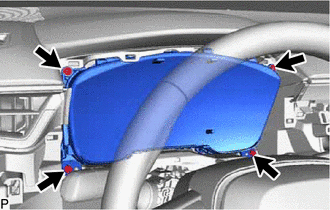
Remove the 4 screws.
for Optitron Meter Type:
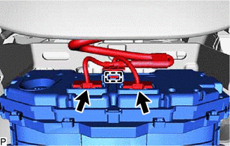
Disengage the clamp.
Disconnect the 2 connectors to remove the combination meter assembly.
for TFT Meter Type:
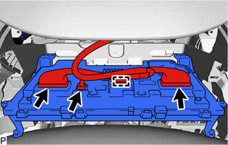
Disengage the clamp.
Disconnect each connector to remove the combination meter assembly.