HEATING / AIR CONDITIONING AIR CONDITIONING UNIT(for Gasoline Model) INSTALLATION
PROCEDURE

 1.TEMPORARILY INSTALL AIR CONDITIONER UNIT ASSEMBLY
2.INSTALL INSTRUMENT PANEL REINFORCEMENT ASSEMBLY WITH AIR CONDITIONER UNIT ASSEMBLY
- NOTICE:
- ·
Be sure to support the air conditioner unit assembly when installing it. Failure to do so may cause the bracket of the air conditioner unit assembly to break.
·When installing the air conditioner unit assembly, eliminate static electricity by touching the vehicle body to prevent the components from being damaged.
Connect each connector.
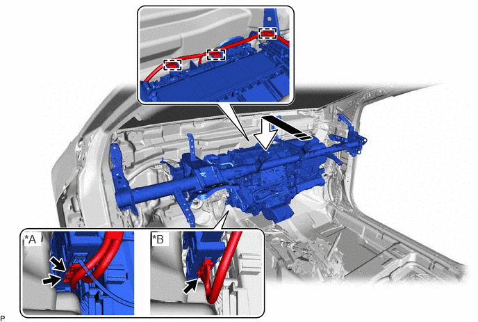
| *A | for Automatic Air Conditioning System | *B | for Manual Air Conditioning System |

|
Install in this Direction | - | - |
Engage each clamp.
Temporarily install the instrument panel reinforcement assembly with air conditioner unit assembly as shown in the illustration.
Install the 4 bolts (A).
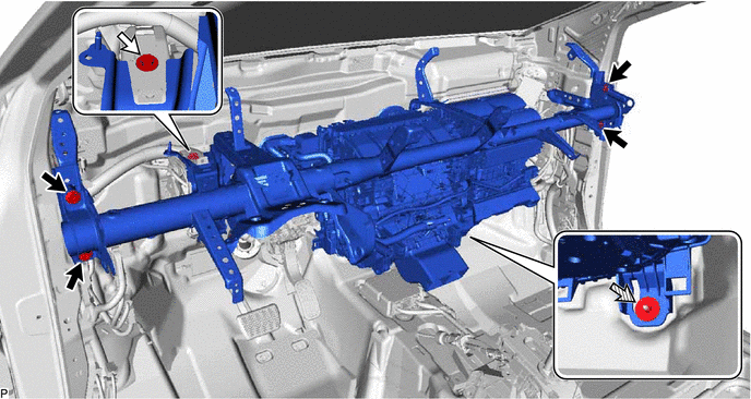

|
Bolt (A) | 
|
Bolt (B) |

|
Nut | - | - |
- Torque:
- 25 N*m (255 kgf*cm, 18 ft.*lbf)
Install the bolt (B).
- Torque:
- 23.6 N*m (241 kgf*cm, 17 ft.*lbf)
Temporarily install the nut.
Install the 2 bolts.
- Torque:
- 25 N*m (255 kgf*cm, 18 ft.*lbf)
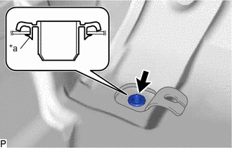
| *a | Lip |
Install a new cooler unit drain hose grommet.
- NOTICE:
- ·
If the drain cooler hose is disconnected from the cooler unit drain hose grommet, make sure to replace the cooler unit drain hose grommet with a new one. Failure to do so may lead to water ingress.
·Make sure that the entire lip of the cooler unit drain hose grommet is securely engaged to the vehicle body.
Connect the drain cooler hose.
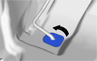
Install the front floor mat to its original position as shown in the illustration.
55307C
3.INSTALL NO. 2 INSTRUMENT PANEL BRACE SUB-ASSEMBLY
Install the No. 2 instrument panel brace sub-assembly with the bolt and nut.
- Torque:
- Bolt : 20 N*m (204 kgf*cm, 15 ft.*lbf)
- Nut : 18 N*m (184 kgf*cm, 13 ft.*lbf)
Temporarily install the screw.
- HINT:
-
Do not fully tighten the screw.
for Manual Air Conditioning System:
Connect the connector.
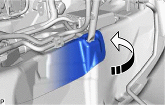
Engage each clamp.
|
|
Move in this Direction |
Install the front floor mat to its original position as shown in the illustration.
55306A
4.INSTALL NO. 1 INSTRUMENT PANEL BRACE SUB-ASSEMBLY
5.INSTALL AIR CONDITIONER UNIT ASSEMBLY
6.CONNECT INSTRUMENT PANEL WIRE (for COROLLA, LEVIN)
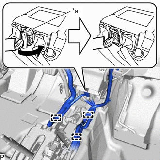
| *a | Lock Lever |
|
|
Move in this Direction |
Engage each clamp.
Temporarily connect the connector and then move the lock lever as shown in the illustration to securely connect the connector.
- NOTICE:
-
When connecting any airbag connector, take care not to damage the airbag wire harness.
Check that there is no looseness in the installed parts of the airbag sensor with ECU assembly.
Engage each clamp.
Connect the instrument panel wire with the screw.
- Torque:
- 3.2 N*m (33 kgf*cm, 28 in.*lbf)
Connect each earth wire with each bolt.
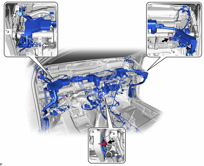
| *A | w/ PTC Heater | - | - |
| *a | Earth Wire | - | - |
|
|
Bolt (A) |
|
Bolt (B) |
- Torque:
- Bolt (A) : 8.8 N*m (90 kgf*cm, 78 in.*lbf)
- Bolt (B) : 8.5 N*m (87 kgf*cm, 75 in.*lbf)
w/ PTC Heater:
Connect the earth wire with the bolt.
- Torque:
- 8.8 N*m (90 kgf*cm, 78 in.*lbf)
Connect each connector.
Connect the instrument panel wire with the bolt.
- Torque:
- 8.8 N*m (90 kgf*cm, 78 in.*lbf)
Connect the relay block holder with the 2 nuts.
- Torque:
- 8.0 N*m (82 kgf*cm, 71 in.*lbf)
7.CONNECT INSTRUMENT PANEL WIRE (for LEVIN GT)
| *a | Lock Lever |
|
|
Move in this Direction |
Engage each clamp.
Temporarily connect the connector and then move the lock lever as shown in the illustration to securely connect the connector.
- NOTICE:
-
When connecting any airbag connector, take care not to damage the airbag wire harness.
Check that there is no looseness in the installed parts of the airbag sensor with ECU assembly.
Engage each clamp.
Connect 3 earth wires with 3 bolts.
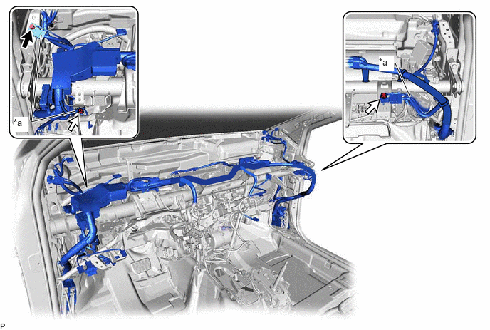
| *a | Earth Wire | - | - |
|
|
Bolt (A) |
|
Bolt (B) |
- Torque:
- Bolt (A) : 8.5 N*m (87 kgf*cm, 75 in.*lbf)
- Bolt (B) : 8.8 N*m (90 kgf*cm, 78 in.*lbf)
Connect the connector.
8.CONNECT INSTRUMENT PANEL WIRE (for ALLION)
| *a | Lock Lever |
|
|
Move in this Direction |
Engage each clamp.
Temporarily connect the connector and then move the lock lever as shown in the illustration to securely connect the connector.
- NOTICE:
-
When connecting any airbag connector, take care not to damage the airbag wire harness.
Check that there is no looseness in the installed parts of the airbag sensor with ECU assembly.
Engage each clamp.
Connect 3 earth wires with 3 bolts.
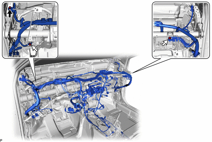
| *a | Earth Wire | - | - |
|
|
Bolt (A) |
|
Bolt (B) |
- Torque:
- Bolt (A) : 8.5 N*m (87 kgf*cm, 75 in.*lbf)
- Bolt (B) : 8.8 N*m (90 kgf*cm, 78 in.*lbf)
Connect the connector.
9.INSTALL DRIVER SIDE JUNCTION BLOCK ASSEMBLY WITH MAIN BODY ECU (for NR Series Engine)
10.INSTALL POWER DISTRIBUTION BOX ASSEMBLY WITH MAIN BODY ECU (except NR Series Engine)
55308B
11.INSTALL NO. 3 INSTRUMENT PANEL TO COWL BRACE SUB-ASSEMBLY
55990B
12.INSTALL LOWER DEFROSTER NOZZLE ASSEMBLY
55086A
13.INSTALL CENTER HEATER TO REGISTER DUCT SUB-ASSEMBLY
55215D
14.INSTALL NO. 3 DASH PANEL INSULATOR PAD
58861B
15.INSTALL NO. 1 CONSOLE BOX DUCT (w/ Rear Air Duct)
58862B
16.INSTALL NO. 2 CONSOLE BOX DUCT (w/ Rear Air Duct)
87212F
17.INSTALL REAR NO. 2 AIR DUCT
87212J
18.INSTALL REAR NO. 5 AIR DUCT
87212K
19.INSTALL REAR NO. 6 AIR DUCT
87212G
20.INSTALL REAR NO. 3 AIR DUCT
87212H
21.INSTALL REAR NO. 4 AIR DUCT
58510D
22.CONNECT FRONT FLOOR CARPET ASSEMBLY
58569D
23.INSTALL FRONT FLOOR CAUTION PLATE COVER
77306
24.INSTALL FUEL LID LOCK OPEN LEVER SUB-ASSEMBLY
88625Q
25.INSTALL COOLER (ROOM TEMP. SENSOR) THERMISTOR (for Automatic Air Conditioning System)
82877
26.INSTALL ECU INTEGRATION BOX RH
89340A
27.INSTALL CLEARANCE WARNING ECU ASSEMBLY (w/ TOYOTA Parking Assist-sensor System)
28.INSTALL INSTRUMENT PANEL SAFETY PAD SUB-ASSEMBLY
29.INSTALL STEERING COLUMN ASSEMBLY
30.INSTALL FRONT SEAT ASSEMBLY LH
for Manual Seat:
for Power Seat:
31.INSTALL FRONT SEAT ASSEMBLY RH
- HINT:
-
Use the same procedure as for the LH side.
88716A
32.CONNECT COOLER REFRIGERANT LIQUID PIPE A
Remove the vinyl tape from the cooler refrigerant liquid pipe A.
Sufficiently apply compressor oil to a new O-ring and the fitting surface of the cooler refrigerant liquid pipe A.
- Compressor Oil:
ND-OIL 8 or equivalent
Install the O-ring to the cooler refrigerant liquid pipe A.
- NOTICE:
-
Keep the O-ring and O-ring fitting surface free of foreign matter.
Connect the cooler refrigerant liquid pipe A.
88707
33.CONNECT SUCTION PIPE SUB-ASSEMBLY
Remove the vinyl tape from the suction pipe sub-assembly.
Sufficiently apply compressor oil to a new O-ring and the fitting surface of the suction pipe sub-assembly.
- Compressor Oil:
ND-OIL 8 or equivalent
Install the O-ring to the suction pipe sub-assembly.
- NOTICE:
-
Keep the O-ring and O-ring fitting surface free of foreign matter.
Connect the suction pipe sub-assembly.
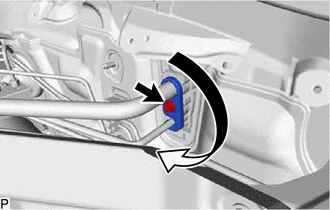
Rotate the hook connector as shown in the illustration.
Insert the tube joint into the fitting hole securely and temporarily install the bolt.
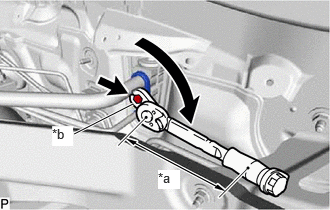
| *a | Torque Wrench Fulcrum Length |
| *b | Union Nut Wrench |
Using a union nut wrench, tighten the bolt.
- Torque:
- Specified tightening torque : 9.8 N*m (100 kgf*cm, 87 in.*lbf)
- HINT:
- ·
Calculate the torque wrench reading when changing the fulcrum length of the torque wrench.
·When using a union nut wrench (fulcrum length of 22 mm (0.866 in.)) + torque wrench (fulcrum length of 162 mm (6.38 in.)):
8.6 N*m (88 kgf*cm, 76 in.*lbf)
87245
34.CONNECT INLET HEATER WATER HOSE (except M15B-FKS, M15C-FKS)
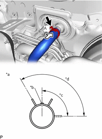
| *a | View A |
| *b | Marking (White) |
| *c | Clip Installation Angle (90°) |
| *d | Clip Installation Angle (120°) |
Connect the inlet heater water hose with the marking facing up and engage the clip within the area shown in the illustration.
- NOTICE:
-
Do not apply excessive force to the inlet heater water hose.
87245
35.CONNECT INLET HEATER WATER HOSE (for M15B-FKS, M15C-FKS)
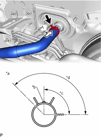
| *a | View A |
| *b | Marking (Red) |
| *c | Clip Installation Angle (90°) |
| *d | Clip Installation Angle (135°) |
Connect the inlet heater water hose with the marking facing up and engage the clip within the area shown in the illustration.
- NOTICE:
-
Do not apply excessive force to the inlet heater water hose.
87246
36.CONNECT OUTLET HEATER WATER HOSE (except M15B-FKS, M15C-FKS)
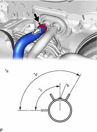
| *a | View A |
| *b | for NR Series Engine TFTM Made:
Marking (White) for NR Series Engine GTMC Made: Marking (Green) for M20A-FKS, M20E-FKS: Marking (Yellow) for M20C-FKS: Marking (Blue) |
| *c | Clip Installation Angle (90°) |
| *d | Clip Installation Angle (120°) |
Connect the outlet heater water hose with the marking facing up and engage the clip within the area shown in the illustration.
- NOTICE:
-
Do not apply excessive force to the outlet heater water hose.
87246
37.CONNECT OUTLET HEATER WATER HOSE (for M15B-FKS, M15C-FKS)
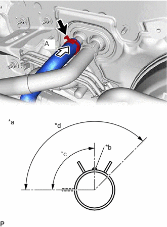
| *a | View A |
| *b | Marking (Yellow) |
| *c | Clip Installation Angle (90°) |
| *d | Clip Installation Angle (135°) |
Connect the outlet heater water hose with the marking facing up and engage the clip within the area shown in the illustration.
- NOTICE:
-
Do not apply excessive force to the outlet heater water hose.
55701J
38.INSTALL OUTER COWL TOP PANEL SUB-ASSEMBLY
55737B
39.INSTALL NO. 1 HEATER AIR DUCT SPLASH SHIELD SEAL (w/ No. 1 Heater Air Duct Splash Shield Seal)
40.INSTALL WINDSHIELD WIPER MOTOR AND LINK ASSEMBLY
41.ADD ENGINE COOLANT
for NR Series Engine:
for M15B-FKS:
for M15C-FKS:
for M20A-FKS:
for M20C-FKS:
for M20E-FKS:
42.INSPECT FOR COOLANT LEAK
for NR Series Engine:
for M15B-FKS:
for M15C-FKS:
for M20A-FKS:
for M20C-FKS:
for M20E-FKS:
43.CHARGE AIR CONDITIONING SYSTEM WITH REFRIGERANT
44.WARM UP ENGINE
45.INSPECT FOR REFRIGERANT LEAK