STEERING COLUMN STEERING COLUMN ASSEMBLY INSTALLATION
PROCEDURE

 1.ALIGN FRONT WHEELS FACING STRAIGHT AHEAD
2.INSTALL STEERING COLUMN ASSEMBLY
- NOTICE:
-
Make sure that the wire harness is not interfering with the steering column assembly.
Install the steering column assembly with the bolt and 2 nuts.
- Torque:
- 36 N*m (367 kgf*cm, 27 ft.*lbf)
- NOTICE:
- ·
After the column is installed, check the tilt operation.
·If a large amount of force is required to operate the tilt mechanism or abnormal noise occurs, loosen the nuts and move the bracket forward or backward until the tilt operation works smoothly.
Tighten the nuts and check the tilt operation again.
Connect each connector and engage each wire harness clamp to the steering column assembly.
84340
3.INSTALL STOP LIGHT SWITCH ASSEMBLY
45260
4.INSTALL NO. 2 STEERING INTERMEDIATE SHAFT ASSEMBLY
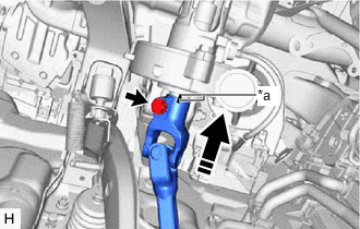
| *a | Matchmark |

|
Install in this direction |
Align the matchmarks on the No. 2 steering intermediate shaft assembly and steering column assembly.
Install the No. 2 steering intermediate shaft assembly to the steering column assembly.
Install the bolt.
- Torque:
- 64 N*m (653 kgf*cm, 47 ft.*lbf)
45260
5.CONNECT NO. 2 STEERING INTERMEDIATE SHAFT ASSEMBLY
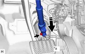
| *a | Matchmark |
|
|
Connect in this direction |
Align the matchmarks on the No. 2 steering intermediate shaft assembly and steering gear assembly.
Connect the No. 2 steering intermediate shaft assembly to the steering gear assembly.
Install the bolt.
- Torque:
- 64 N*m (653 kgf*cm, 47 ft.*lbf)
45259A
6.INSTALL COLUMN HOLE COVER SILENCER SHEET
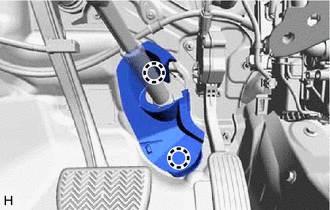
Engage the 2 claws to install the column hole cover silencer sheet.
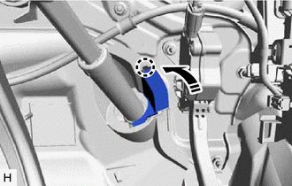
|
|
Close in this direction |
Engage the claw to close the column hole cover silencer sheet.
87211
7.INSTALL NO. 1 AIR DUCT
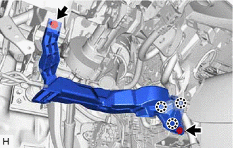
Engage the 3 claws to install a new No. 1 air duct.
Install the 2 bolts.
58831A
8.INSTALL FRONT CONSOLE UPPER PANEL GARNISH
58816D
9.INSTALL FRONT NO. 1 CONSOLE BOX INSERT
55432B
10.INSTALL LOWER INSTRUMENT PANEL FINISH PANEL (w/o Knee Airbag)
53601
11.CONNECT HOOD LOCK CONTROL LEVER SUB-ASSEMBLY (w/o Knee Airbag)
55434F
12.INSTALL LOWER CENTER INSTRUMENT PANEL FINISH PANEL (w/o Knee Airbag)
55317E
13.INSTALL NO. 1 INSTRUMENT SIDE PANEL (w/o Knee Airbag)
55606
14.INSTALL NO. 1 INSTRUMENT PANEL UNDER COVER SUB-ASSEMBLY (w/o Knee Airbag)
62112A
15.INSTALL COWL SIDE TRIM SUB-ASSEMBLY LH (w/o Knee Airbag)
67914
16.INSTALL FRONT DOOR SCUFF PLATE LH (w/o Knee Airbag)
73900
17.INSTALL LOWER NO. 1 INSTRUMENT PANEL AIRBAG ASSEMBLY (w/ Knee Airbag)
18.INSTALL TURN SIGNAL SWITCH ASSEMBLY WITH SPIRAL CABLE SUB-ASSEMBLY
- NOTICE:
- ·
Do not remove/install the spiral cable with sensor sub-assembly with the auxiliary battery connected and the ignition switch (for Gasoline Model) or power switch (for HV Model) on (IG).
·Do not rotate the spiral cable with sensor sub-assembly without the steering wheel assembly installed, with the auxiliary battery connected and the ignition switch (for Gasoline Model) or power switch (for HV Model) on (IG).
·Ensure that the steering wheel is installed and aligned straight when inspecting the steering sensor.
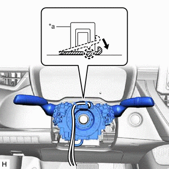
| *a | Clamp |
Using pliers, expand the clamp.
While holding the clamp expanded, install the turn signal switch assembly with spiral cable sub-assembly to the steering column assembly and engage the claw.
Return the clamp to its original position.
Connect each connector to the turn signal switch assembly with spiral cable sub-assembly.
89782
19.INSTALL TRANSPONDER KEY COIL (w/o Smart Entry and Start System)
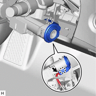
Engage the 2 claws to install the transponder key coil.
Connect the connector.
45286B
20.INSTALL UPPER STEERING COLUMN COVER
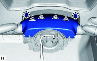
Engage the 2 claws and 4 clips to connect the upper steering column cover.
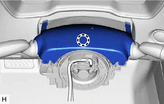
Engage the claw to install the upper steering column cover.
45287
21.INSTALL LOWER STEERING COLUMN COVER
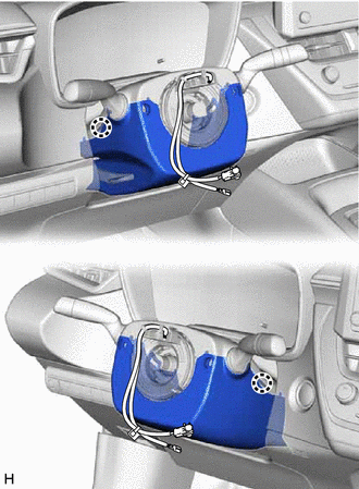
Engage the 2 claws to install the lower steering column cover.
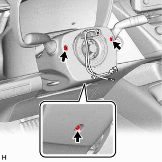
Install the 3 screws.
22.ALIGN FRONT WHEELS FACING STRAIGHT AHEAD
23.INSPECT AND ADJUST SPIRAL CABLE WITH SENSOR SUB-ASSEMBLY
24.INSTALL STEERING WHEEL ASSEMBLY
25.CHECK STEERING WHEEL CENTER POINT
45130
26.INSTALL HORN BUTTON ASSEMBLY
27. UPDATE ECU SECURITY KEY (except NR Series Engine)
- HINT:
-
After replacing the power steering ECU assembly, make sure to perform update ECU security key.
28. ECU CONFIGURATION (except NR Series Engine)
- HINT:
-
After replacing the power steering ECU assembly, make sure to perform ECU configuration.
29. PERFORM POWER STEERING ECU INITIAL SETTING (ASSIST MAP WRITING)
for HV Model: Click hereSteering>POWER ASSIST SYSTEMS>POWER STEERING SYSTEM (for HV Model)>CALIBRATION202304,202307,_55,_080761,_0392075,RM100000002B8OH,202307,999999,_55,_080761,_0392075,RM100000002CNVO,
for Gasoline Model, except NR Series: Click hereSteering>POWER ASSIST SYSTEMS>POWER STEERING SYSTEM (for Gasoline Model)>CALIBRATION202304,999999,_55,_080761,_0392052,RM100000002B8PZ,
30. PERFORM POWER STEERING ECU INITIAL SETTING (TORQUE SENSOR ZERO POINT CALIBRATION AND ASSIST MAP WRITING) (for NR Series)
31. PERFORM END POSITION INITIAL SETTING
for HV Model: Click hereSteering>POWER ASSIST SYSTEMS>POWER STEERING SYSTEM (for HV Model)>CALIBRATION202304,202307,_55,_080761,_0392075,RM100000002B8OH,202307,999999,_55,_080761,_0392075,RM100000002CNVO,
for Gasoline Model, except NR Series: Click hereSteering>POWER ASSIST SYSTEMS>POWER STEERING SYSTEM (for Gasoline Model)>CALIBRATION202304,999999,_55,_080761,_0392052,RM100000002B8PZ,