HEATING / AIR CONDITIONING AIR CONDITIONING SYSTEM(for Gasoline Model (NR Series) with Manual Air Conditioning System for Mechanical Control Type) Recirculated/Fresh Air Modes do not Switch
DESCRIPTION
If the air inlet mode cannot be changed between recirculation/fresh or exhaust gas odors can be smelled even though recirculation mode is selected, the following factors may be the cause.
| Symptom | Factor |
|---|---|
·
Air inlet mode cannot be changed between recirculation/fresh ·
Exhaust gas odors can be smelled when air inlet mode set to recirculation mode |
·
No. 1 blower damper servo sub-assembly malfunction ·
No. 2 heater control sub-assembly malfunction ·
Harness or connector |
WIRING DIAGRAM
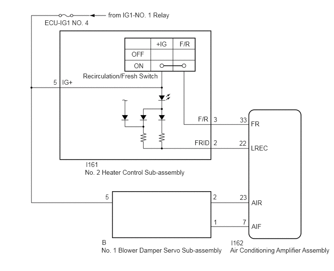
CAUTION / NOTICE / HINT
- NOTICE:
-
Inspect the fuses for circuits related to this system before performing the following procedure.
PROCEDURE
Check that the No. 1 blower damper servo sub-assembly is installed correctly.
- OK:
The No. 1 blower damper servo sub-assembly is installed correctly.
- Result:
Proceed to OK NG
OK
NG
Remove the No. 1 blower damper servo sub-assembly.
Inspect the No. 1 blower damper servo sub-assembly.
- Result:
Proceed to OK NG
OK
NG
Remove the No. 2 heater control sub-assembly.
Inspect the No. 2 heater control sub-assembly.
- Result:
Proceed to OK NG
OK
NG
Disconnect the I161 No. 2 heater control sub-assembly connector.
Measure the voltage according to the value(s) in the table below.
- Standard Voltage:
Tester Connection Condition Specified Condition I161-5 (IG+) - Body ground Ignition switch off Below 1 V I161-5 (IG+) - Body ground Ignition switch on (IG) 11 to 14 V
- Result:
Proceed to OK NG
OK
NG
Disconnect the I162 air conditioning amplifier assembly connector.
Measure the resistance according to the value(s) in the table below.
- Standard Resistance:
Tester Connection Condition Specified Condition I161-2 (FRID) - I162-22 (LREC) Always Below 1 Ω I161-3 (F/R) - I162-33 (FR) Always Below 1 Ω I161-2 (FRID) - I162-22 (LREC) - Other terminals and body ground Always 10 kΩ or higher I161-3 (F/R) - I162-33 (FR) - Other terminals and body ground Always 10 kΩ or higher
- Result:
Proceed to OK NG
OK
NG
Disconnect the B No. 1 blower damper servo sub-assembly connector.
Measure the voltage according to the value(s) in the table below.
- Standard Voltage:
Tester Connection Condition Specified Condition B-5 - Body ground Ignition switch off Below 1 V B-5 - Body ground Ignition switch on (IG) 11 to 14 V
- Result:
Proceed to OK NG
OK
NG
Measure the resistance according to the value(s) in the table below.
- Standard Resistance:
Tester Connection Condition Specified Condition B-2 - I162-23 (AIR) Always Below 1 Ω B-1 - I162-7 (AIF) Always Below 1 Ω B-2 or I162-23 (AIR) - Other terminals and body ground Always 10 kΩ or higher B-1 or I162-7 (AIF) - Other terminals and body ground Always 10 kΩ or higher
- Result:
Proceed to OK NG
OK
NG