HEATING / AIR CONDITIONING AIR CONDITIONING PANEL INSPECTION
PROCEDURE

 1.INSPECT NO. 1 HEATER CONTROL SUB-ASSEMBLY (for Mechanical Control Type)
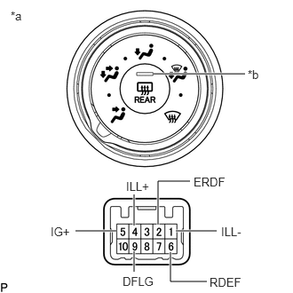
| *a | Component without harness connected
(No. 1 Heater Control Sub-assembly) |
| *b | Window Defogger Switch Indicator |
Measure the resistance according to the value(s) in the table below.
- Standard Resistance:
Tester Connection Switch Position Specified Condition 5 (IG+) - 9 (DFLG) DEF / FOOT Switch, DEF Switch Below 1 Ω
If the result is not as specified, replace the No. 1 heater control sub-assembly.
Check the illumination.
Apply battery voltage to the connector terminal and check the illumination.
- OK:
Measurement Condition Specified Condition Battery positive (+) → 4 (ILL+)
Battery negative (-) → 1 (ILL-)No. 1 heater control sub-assembly illuminates
If the result is not as specified, replace the No. 1 heater control sub-assembly.
Check the indicator.
Apply battery voltage to the connector terminal and check the indicator.
- OK:
Measurement Condition Switch Position Specified Condition Battery positive (+) → 5 (IG+), RDEF (6)
Battery negative (-) → 2 (ERDF)Window Defogger Switch ON position Indicator illuminates Window Defogger Switch OFF position Indicator does not illuminate
If the result is not as specified, replace the No. 1 heater control sub-assembly.
2.INSPECT NO. 2 HEATER CONTROL SUB-ASSEMBLY (for Mechanical Control Type)
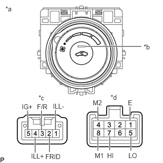
| *a | Component without harness connected
(No. 2 Heater Control Sub-assembly) |
| *b | Fresh/recirculation Switch Indicator |
| *c | Connector A |
| *d | Connector B |
Measure the resistance according to the value(s) in the table below.
- Standard Resistance:
Tester Connection Switch Position Specified Condition B-5 (LO), B-8 (M1), B-4 (M2), B-7 (HI) - B-1 (E) Blower switch: 0 10 kΩ or higher B-5 (LO) - B-1 (E) Blower switch: LO Below 1 Ω B-5 (LO), B-8 (M1) - B-1 (E) Blower switch: LO - M1 Below 1 Ω B-5 (LO), B-8 (M1) - B-1 (E) Blower switch: M1 Below 1 Ω B-5 (LO), B-8 (M1), B4 (M2) - B-1 (E) Blower switch: M1 - M2 Below 1 Ω B-5 (LO), B-4 (M2) - B-1 (E) Blower switch: M2 Below 1 Ω B-5 (LO), B-4 (M2), B-7 (HI) - B-1 (E) Blower switch: M2 - HI Below 1 Ω B-5 (LO), B-7 (HI) - B-1 (E) Blower switch: HI Below 1 Ω A-5 (IG+) - A-3 (F/R) Fresh/recirculation switch ON position Below 1 Ω A-5 (IG+) - A-3 (F/R) Fresh/recirculation switch OFF position 10 kΩ or higher
If the result is not as specified, replace the No. 2 heater control sub-assembly.
Check the illumination.
Apply battery voltage to the connector terminal and check the illumination.
- OK:
Measurement Condition Specified Condition Battery positive (+) → A-4 (ILL+)
Battery negative (-) → A-1 (ILL-)No. 2 Heater control sub-assembly illuminates
If the result is not as specified, replace the No. 2 heater control sub-assembly.
Check the fresh/recirculation switch indicator.
Apply battery voltage to the air conditioning control assembly (fresh/recirculation switch) and check that the indicator.
- OK:
Measurement Condition Switch Position Specified Condition Battery positive (+) → A-5 (IG+)
Battery negative (-) → A-2 (FRID)fresh/recirculation switch ON position Indicator illuminates fresh/recirculation switch OFF position Indicator does not illuminate
If the result is not as specified, replace the No. 2 heater control sub-assembly.
3.INSPECT NO. 3 HEATER CONTROL SUB-ASSEMBLY (for Mechanical Control Type)
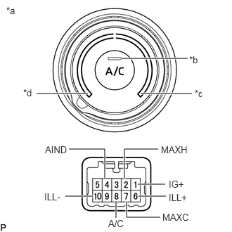
| *a | Component without harness connected
(No. 3 Heater Control Sub-assembly) |
| *b | A/C Switch Indicator |
| *c | MAX HOT |
| *d | MAX COLD |
Measure the resistance according to the value(s) in the table below.
- Standard Resistance:
Tester Connection Switch Condition Specified Condition 1 (IG+) - 2 (MAXH) Except MAX HOT 10 kΩ or higher 1 (IG+) - 2 (MAXH) MAX HOT Below 1 Ω 1 (IG+) - 7 (MAXC) Except MAX COLD 10 kΩ or higher 1 (IG+) - 7 (MAXC) MAX COLD Below 1 Ω 1 (IG+) - 8 (A/C) A/C switch ON position Below 1 Ω 1 (IG+) - 8 (A/C) A/C switch OFF position 10 kΩ or higher
If the result is not as specified, replace the No. 3 heater control sub-assembly.
Check the illumination.
Apply battery voltage to the connector terminal and check the illumination.
- OK:
Measurement Condition Specified Condition Battery positive (+) → 6 (ILL+)
Battery negative (-) → 10 (ILL-)No. 3 heater control sub-assembly illuminates
If the result is not as specified, replace the No. 3 heater control sub-assembly.
Check the indicator.
Apply battery voltage to the connector terminal and check the indicator.
- OK:
Measurement Condition Switch Position Specified Condition Battery positive (+) → 1 (IG+)
Battery negative (-) → 4 (AIND)A/C switch: ON Indicator illuminates A/C switch: OFF Indicator does not illuminate
If the result is not as specified, replace the No. 3 heater control sub-assembly.