RM35X0E _56 Audio / Visual / Telematics _078379 NAVIGATION / MULTI INFO DISPLAY _0380999 NAVIGATION SYSTEM C

NAVIGATION / MULTI INFO DISPLAY  NAVIGATION SYSTEM  B1579  Voice Recognition Microphone Disconnected  


DESCRIPTION

The radio and display receiver assembly, map light assembly and telephone microphone assembly are connected to each other using the microphone connection detection signal lines.

This DTC is stored when a microphone connection detection signal line is disconnected.

DTC No. Detection Item DTC Detection Condition Trouble Area
B1579 Voice Recognition Microphone Disconnected Microphone signal is lost
·

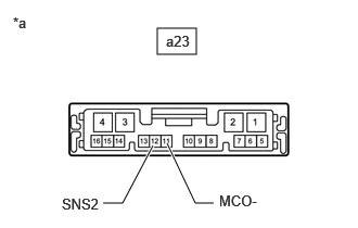
Map light assembly

·

Telephone microphone assembly

·

Radio and display receiver assembly

·

Harness or connector


WIRING DIAGRAM

E418257
1.49,0.792 2.781,1.208 1.292,0.417 10 false SNS2 1.563,1.792 2.854,2.208 1.292,0.417 10 false MIC- 1.948,0.708 3.24,1.125 1.292,0.417 10 false 1 1.948,1.698 3.24,2.115 1.292,0.417 10 false 2 1.115,2.073 2.406,2.49 1.292,0.417 10 false A*1, B*2 2.5,0.688 3.792,1.104 1.292,0.417 10 false SNS2 2.479,1.698 3.771,2.115 1.292,0.417 10 false MCO- 2.948,0.333 4.24,0.75 1.292,0.417 10 false 11*1 2.948,1.354 4.24,1.771 1.292,0.417 10 false 10*1 5.375,0.688 6.667,1.104 1.292,0.417 10 false 25 5.365,1.688 6.656,2.104 1.292,0.417 10 false 22 5.646,0.813 6.938,1.229 1.292,0.417 10 false SNS2 5.635,1.813 6.927,2.229 1.292,0.417 10 false MIN- 1.094,2.229 2.51,2.667 1.417,0.438 10 false Telephone Microphone Assembly 5.438,2.5 6.667,2.99 1.229,0.49 10 false Radio and Display Receiver Assembly 5.427,2.333 6.656,2.823 1.229,0.49 10 false O7 0.792,2.958 2.208,3.365 1.417,0.406 10 false a19*1, a22*3, a23*4 0.802,3.146 2.396,3.49 1.594,0.344 10 false Map Light Assembly 0.313,3.906 1.604,4.323 1.292,0.417 10 false *1: except Wagon 0.323,4.271 1.615,4.688 1.292,0.417 10 false *2: for Wagon 1.688,3.938 6.896,4.219 5.208,0.281 10 false *3: for Wagon and w/ Telematics Transceiver (for Toyota Connected Services) 1.698,4.292 5.021,4.625 3.323,0.333 10 false *4: for Wagon and w/o Telematics Transceiver 3.031,0.51 4.323,0.927 1.292,0.417 10 false 3*3 2.958,0.688 4.25,1.104 1.292,0.417 10 false 12*4 3.031,1.521 4.323,1.938 1.292,0.417 10 false 4*3 2.948,1.698 4.24,2.115 1.292,0.417 10 false 11*4

CAUTION / NOTICE / HINT

HINT:

Depending on the parts that are replaced during vehicle inspection or maintenance, performing initialization, registration or calibration may be needed. Refer to Precaution for Navigation System.

Click hereAudio / Visual / Telematics>NAVIGATION / MULTI INFO DISPLAY>NAVIGATION SYSTEM>PRECAUTION


PROCEDURE

1.CHECK MODEL
a.

Choose the model to be inspected.

Result:
Result Proceed to
except Wagon A
for Wagon and w/ Telematics Transceiver (for Toyota Connected Services) B
for Wagon and w/o Telematics Transceiver C


A

2.CHECK HARNESS AND CONNECTOR (RADIO AND DISPLAY RECEIVER ASSEMBLY - MAP LIGHT ASSEMBLY)

B

5.CHECK HARNESS AND CONNECTOR (RADIO AND DISPLAY RECEIVER ASSEMBLY - MAP LIGHT ASSEMBLY)

C

8.CHECK HARNESS AND CONNECTOR (RADIO AND DISPLAY RECEIVER ASSEMBLY - MAP LIGHT ASSEMBLY)
2.CHECK HARNESS AND CONNECTOR (RADIO AND DISPLAY RECEIVER ASSEMBLY - MAP LIGHT ASSEMBLY)
a.

Disconnect the O7 radio and display receiver assembly connector.


b.

Disconnect the a19 map light assembly connector.


c.

Measure the resistance according to the value(s) in the table below.

Standard Resistance:
Tester Connection Condition Specified Condition
O7-25 (SNS2) - a19-11 (SNS2) Always Below 1 Ω
O7-22 (MIN-) - a19-10 (MCO-) Always Below 1 Ω
O7-25 (SNS2) - Body ground Always 10 kΩ or higher
O7-22 (MIN-) - Body ground Always 10 kΩ or higher


Result:
Proceed to
OK
NG


OK

3.INSPECT MAP LIGHT ASSEMBLY

NG

REPAIR OR REPLACE HARNESS OR CONNECTOR

3.INSPECT MAP LIGHT ASSEMBLY
a.
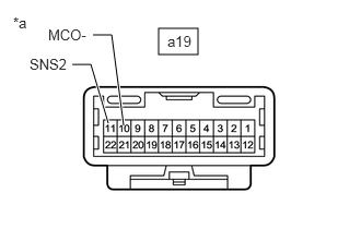
E408533C02
1.51,0.271 1.885,0.521 0.375,0.25 1.177,1.198 1.063,0.333 1.063,0.333 0.885,0.333 true 1.031,1.177 0.865,0.615 0.865,0.615 0.688,0.615 true 0.125,0.135 0.438,0.333 0.313,0.198 10 false *a 0.458,0.25 0.969,0.458 0.51,0.208 10 false MCO- 0.281,0.531 0.813,0.792 0.531,0.26 10 false SNS2 1.594,0.313 1.906,0.51 0.313,0.198 10 false a19
*a Component without harness connected
(Map Light Assembly)


Remove the map light assembly.

Click hereVehicle Interior>LIGHTING (INT)>PERSONAL LIGHT>REMOVAL


b.

Measure the resistance according to the value(s) in the table below.

Standard Resistance:
Tester Connection Condition Specified Condition
a19-11 (SNS2) - a19-10 (MCO-) Always Below 1 Ω


Result:
Proceed to
OK
NG


OK

NG

4.INSPECT MAP LIGHT ASSEMBLY
a.
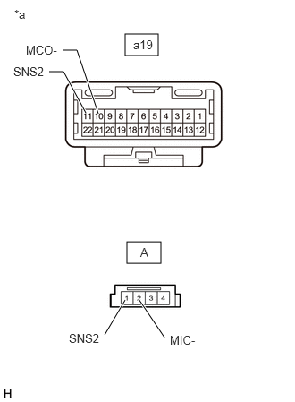
E408555C03
1.458,0.396 1.844,0.646 0.385,0.25 1.479,2.813 1.875,3.063 0.396,0.25 1,1.313 0.74,0.833 0.74,0.833 0.573,0.833 true 1.458,3.49 1.219,3.896 true 1.917,3.927 1.615,3.479 true 1.146,1.323 0.896,0.583 0.896,0.583 0.729,0.583 true 0.167,0.083 0.479,0.281 0.313,0.198 10 false *a 0.156,0.75 0.656,0.969 0.5,0.219 10 false SNS2 0.302,0.5 0.781,0.708 0.479,0.208 10 false MCO- 1.635,2.854 1.948,3.052 0.313,0.198 10 false A 1.552,0.438 2.031,0.646 0.479,0.208 10 false a19 0.802,3.854 1.302,4.073 0.5,0.219 10 false SNS2 1.979,3.875 2.458,4.083 0.479,0.208 10 false MIC-
*a Component without harness connected
(Map Light Assembly)


Remove the map light assembly.

Click hereVehicle Interior>LIGHTING (INT)>PERSONAL LIGHT>REMOVAL


b.

Disconnect the telephone microphone assembly connector.


c.

Measure the resistance according to the value(s) in the table below.

Standard Resistance:
Tester Connection Condition Specified Condition
a19-11 (SNS2) - A-1 (SNS2) Always Below 1 Ω
a19-10 (MCO-) - A-2 (MIC-) Always Below 1 Ω


Result:
Proceed to
OK
NG


OK

NG

5.CHECK HARNESS AND CONNECTOR (RADIO AND DISPLAY RECEIVER ASSEMBLY - MAP LIGHT ASSEMBLY)
a.

Disconnect the O7 radio and display receiver assembly connector.


b.

Disconnect the a22 map light assembly connector.


c.

Measure the resistance according to the value(s) in the table below.

Standard Resistance:
Tester Connection Condition Specified Condition
O7-25 (SNS2) - a22-3 (SNS2) Always Below 1 Ω
O7-22 (MIN-) - a22-4 (MCO-) Always Below 1 Ω
O7-25 (SNS2) - Body ground Always 10 kΩ or higher
O7-22 (MIN-) - Body ground Always 10 kΩ or higher


Result:
Proceed to
OK
NG


OK

6.INSPECT MAP LIGHT ASSEMBLY

NG

REPAIR OR REPLACE HARNESS OR CONNECTOR

6.INSPECT MAP LIGHT ASSEMBLY

b.
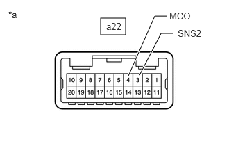
E419871C01
1.51,0.271 1.885,0.521 0.375,0.25 2.094,1.125 2.417,0.5 2.417,0.5 2.594,0.5 true 1.927,1.135 2.323,0.24 2.323,0.24 2.5,0.24 true 0.125,0.135 0.438,0.333 0.313,0.198 10 false *a 2.542,0.156 3.052,0.365 0.51,0.208 10 false MCO- 2.667,0.417 3.198,0.677 0.531,0.26 10 false SNS2 1.594,0.313 1.906,0.51 0.313,0.198 10 false a22
*a Component without harness connected
(Map Light Assembly)


Measure the resistance according to the value(s) in the table below.

Standard Resistance:
Tester Connection Condition Specified Condition
a22-3 (SNS2) - a22-4 (MCO-) Always Below 1 Ω


Result:
Proceed to
OK
NG


OK

NG

7.INSPECT MAP LIGHT ASSEMBLY
a.
E419874C04
1.573,0.396 1.958,0.646 0.385,0.25 1.458,2.813 1.854,3.063 0.396,0.25 1.958,1.406 1.49,0.729 1.49,0.729 1.344,0.729 true 2.104,1.417 2.396,0.604 2.396,0.604 2.552,0.604 true 1.354,3.479 1.104,3.896 1.104,3.896 0.958,3.896 true 1.49,3.49 1.781,3.906 1.781,3.906 1.938,3.906 true 0.198,0.354 0.51,0.552 0.313,0.198 10 false *a 0.906,0.635 1.406,0.854 0.5,0.219 10 false MCO- 2.635,0.542 3.115,0.75 0.479,0.208 10 false SNS2 1.615,2.854 1.927,3.052 0.313,0.198 10 false B 1.635,0.448 2.115,0.656 0.479,0.208 10 false a22 1.979,3.823 2.479,4.042 0.5,0.219 10 false MIC- 0.531,3.823 1.031,4.042 0.5,0.219 10 false SNS2 0.219,2.74 0.531,2.938 0.313,0.198 10 false *b
*a Component without harness connected
(Map Light Assembly [Wire Harness Side])
*b Component without harness connected
(Map Light Assembly [Telephone Microphone Assembly Side])


Remove the map light assembly.

Click hereVehicle Interior>LIGHTING (INT)>PERSONAL LIGHT (for Wagon)>REMOVAL


b.

Disconnect the telephone microphone assembly connector.


c.

Measure the resistance according to the value(s) in the table below.

Standard Resistance:
Tester Connection Condition Specified Condition
a22-3 (SNS2) - B-1 (SNS2) Always Below 1 Ω
a22-4 (MCO-) - B-2 (MIC-) Always Below 1 Ω
a22-3 (SNS2) - Body ground Always 10 kΩ or higher
a22-4 (MCO-) - Body ground Always 10 kΩ or higher


Result:
Proceed to
OK
NG


OK

NG

8.CHECK HARNESS AND CONNECTOR (RADIO AND DISPLAY RECEIVER ASSEMBLY - MAP LIGHT ASSEMBLY)
a.

Disconnect the O7 radio and display receiver assembly connector.


b.

Disconnect the a23 map light assembly connector.


c.

Measure the resistance according to the value(s) in the table below.

Standard Resistance:
Tester Connection Condition Specified Condition
O7-25 (SNS2) - a23-12 (SNS2) Always Below 1 Ω
O7-22 (MIN-) - a23-11 (MCO-) Always Below 1 Ω
O7-25 (SNS2) - Body ground Always 10 kΩ or higher
O7-22 (MIN-) - Body ground Always 10 kΩ or higher


Result:
Proceed to
OK
NG


OK

9.INSPECT MAP LIGHT ASSEMBLY

NG

REPAIR OR REPLACE HARNESS OR CONNECTOR

9.INSPECT MAP LIGHT ASSEMBLY

b.
E419872C01
1.51,0.271 1.885,0.521 0.375,0.25 1.469,1.396 1.177,1.948 1.177,1.948 0.99,1.948 true 1.604,1.375 1.875,1.948 1.875,1.948 2.052,1.948 true 0.125,0.135 0.438,0.333 0.313,0.198 10 false *a 2.104,1.844 2.615,2.052 0.51,0.208 10 false MCO- 0.594,1.875 1.125,2.135 0.531,0.26 10 false SNS2 1.594,0.313 1.906,0.51 0.313,0.198 10 false a23
*a Component without harness connected
(Map Light Assembly)


Measure the resistance according to the value(s) in the table below.

Standard Resistance:
Tester Connection Condition Specified Condition
a23-12 (SNS2) - a23-11 (MCO-) Always Below 1 Ω


Result:
Proceed to
OK
NG


OK

NG

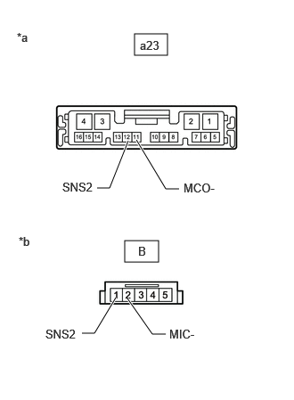
10.INSPECT MAP LIGHT ASSEMBLY
a.
E419875C01
1.573,0.396 1.958,0.646 0.385,0.25 1.458,2.813 1.854,3.063 0.396,0.25 1.5,1.646 1.281,2.198 1.281,2.198 1.135,2.198 true 1.594,1.635 1.938,2.208 1.938,2.208 2.094,2.208 true 1.354,3.479 1.104,3.896 1.104,3.896 0.958,3.896 true 1.49,3.49 1.781,3.906 1.781,3.906 1.938,3.906 true 0.198,0.354 0.51,0.552 0.313,0.198 10 false *a 2.146,2.115 2.646,2.333 0.5,0.219 10 false MCO- 0.729,2.104 1.208,2.313 0.479,0.208 10 false SNS2 1.615,2.854 1.927,3.052 0.313,0.198 10 false B 1.635,0.448 2.115,0.656 0.479,0.208 10 false a23 1.979,3.823 2.479,4.042 0.5,0.219 10 false MIC- 0.531,3.823 1.031,4.042 0.5,0.219 10 false SNS2 0.219,2.74 0.531,2.938 0.313,0.198 10 false *b
*a Component without harness connected
(Map Light Assembly [Wire Harness Side])
*b Component without harness connected
(Map Light Assembly [Telephone Microphone Assembly Side])


Remove the map light assembly.

Click hereVehicle Interior>LIGHTING (INT)>PERSONAL LIGHT (for Wagon)>REMOVAL


b.

Disconnect the telephone microphone assembly connector.


c.

Measure the resistance according to the value(s) in the table below.

Standard Resistance:
Tester Connection Condition Specified Condition
a23-12 (SNS2) - B-1 (SNS2) Always Below 1 Ω
a23-11 (MCO-) - B-2 (MIC-) Always Below 1 Ω
a23-12 (SNS2) - Body ground Always 10 kΩ or higher
a23-11 (MCO-) - Body ground Always 10 kΩ or higher


Result:
Proceed to
OK
NG


OK

NG