RM35X0E _56 Audio / Visual / Telematics _079315 PARK ASSIST / MONITORING _0385738 BLIND SPOT MONITOR SYSTEM C

PARK ASSIST / MONITORING  BLIND SPOT MONITOR SYSTEM  C1AB2  Short to GND in Outer Mirror Indicator(Master)  


DESCRIPTION

This DTC is stored when the blind spot monitor sensor LH detects a short to ground in the outer rear view mirror indicator LH.

DTC No. Detection Item DTC Detection Condition Trouble Area
C1AB2 Short to GND in Outer Mirror Indicator(Master)
Both of the following conditions are met:
·

The blind spot monitor system is on


·

The current that is sent from the blind spot monitor sensor to the indicator is above a specified level for a specified period of time


·

Outer mirror LH (outer rear view mirror indicator LH)

·

Outer mirror retractor LH (w/o Panoramic View Monitor System)

·

Harness or connector

·

Blind spot monitor sensor LH

·

Outer rear view mirror assembly LH (w/ Panoramic View Monitor System)


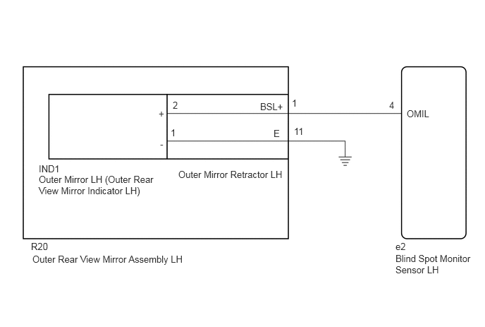
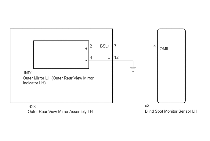
WIRING DIAGRAM

w/o Panoramic View Monitor System
E410127E01
2.552,1.469 2.708,1.667 0.156,0.198 10 false 2 2.521,1.875 2.792,2.083 0.271,0.208 10 false 1 2.344,1.594 2.5,1.792 0.156,0.198 10 false + 2.365,2.042 2.521,2.24 0.156,0.198 10 false - 0.573,2.406 1.229,2.635 0.656,0.229 10 false IND1 0.573,2.563 2.271,3.021 1.698,0.458 10 false Outer Mirror LH (Outer Rear View Mirror Indicator LH) 0.479,3.74 2.958,4.031 2.479,0.292 10 false Outer Rear View Mirror Assembly LH 6.01,1.594 6.479,1.792 0.469,0.198 10 false OMIL 5.75,1.469 6.219,1.667 0.469,0.198 10 false 4 5.844,3.552 6.313,3.75 0.469,0.198 10 false e2 5.844,3.729 7.052,4.344 1.208,0.615 10 false Blind Spot Monitor Sensor LH 0.458,3.552 0.875,3.74 0.417,0.188 10 false R20 3.844,1.49 4.24,1.656 0.396,0.167 10 false BSL+ 4.042,1.885 4.302,2.073 0.26,0.188 10 false E 4.313,1.438 4.604,1.604 0.292,0.167 10 false 1 4.344,1.854 4.635,2.021 0.292,0.167 10 false 11 2.635,2.49 4.375,2.792 1.74,0.302 10 false Outer Mirror Retractor LH

w/ Panoramic View Monitor System
E270468E55
0.781,2.583 3.208,3.01 2.427,0.427 10 false Outer Mirror LH (Outer Rear View Mirror Indicator LH) 0.948,3.729 3.427,3.948 2.479,0.219 10 false Outer Rear View Mirror Assembly LH 0.969,3.563 2.042,3.729 1.073,0.167 10 false R23 3.417,1.49 3.865,1.719 0.448,0.229 10 false BSL+ 3.896,1.49 4.771,1.688 0.875,0.198 10 false 7 3.896,1.875 4.552,2.042 0.656,0.167 10 false 12 3.667,1.875 4.125,2.208 0.458,0.333 10 false E 5.448,1.583 6.063,1.781 0.615,0.198 10 false OMIL 4.948,3.719 6.844,3.958 1.896,0.24 10 false Blind Spot Monitor Sensor LH 4.948,3.521 5.26,3.719 0.313,0.198 10 false e2 5.24,1.49 5.396,1.688 0.156,0.198 10 false 4 3.063,1.49 3.219,1.688 0.156,0.198 10 false 2 3.073,1.896 3.229,2.094 0.156,0.198 10 false 1 2.906,1.573 3.135,1.802 0.229,0.229 10 false + 2.917,1.969 3.073,2.167 0.156,0.198 10 false - 0.813,2.406 1.24,2.615 0.427,0.208 10 false IND1

CAUTION / NOTICE / HINT

NOTICE:

When checking for DTCs, make sure that the blind spot monitor system is turned on.


PROCEDURE

1.CHECK DTC
a.

Recheck for DTCs and check if the same DTC is output again.

Click hereAudio / Visual / Telematics>PARK ASSIST / MONITORING>BLIND SPOT MONITOR SYSTEM>DTC CHECK / CLEAR

Body Electrical > Blind Spot Monitor Master > Trouble Codes
50001 313
OK:

No DTCs are output.


Result:
Result Proceed to
OK A
NG (w/o Panoramic View Monitor System) B
NG (w/ Panoramic View Monitor System) C


A

B

2.CHECK HARNESS AND CONNECTOR (BLIND SPOT MONITOR SENSOR LH - OUTER REAR VIEW MIRROR ASSEMBLY LH)

C

5.CHECK HARNESS AND CONNECTOR (BLIND SPOT MONITOR SENSOR LH - OUTER REAR VIEW MIRROR ASSEMBLY LH)
2.CHECK HARNESS AND CONNECTOR (BLIND SPOT MONITOR SENSOR LH - OUTER REAR VIEW MIRROR ASSEMBLY LH)
a.
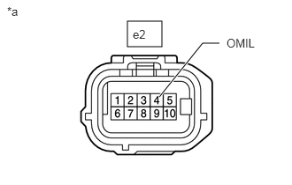
E406932C16
1.5,0.25 1.906,0.552 0.406,0.302 1.875,1.146 2.385,0.51 2.385,0.51 2.583,0.51 true 0.083,0.052 0.396,0.25 0.313,0.198 10 false *a 1.563,0.323 1.875,0.521 0.313,0.198 10 false e2 2.667,0.427 3.073,0.615 0.406,0.188 10 false OMIL
*a Front view of wire harness connector
(to Blind Spot Monitor Sensor LH)


Disconnect the blind spot monitor sensor LH connector.


b.

Disconnect the R20 outer rear view mirror assembly LH connector.


c.

Measure the resistance according to the value(s) in the table below.

Standard Resistance:
Tester Connection Condition Always
e2-4 (OMIL) - Body ground Always 10 kΩ or higher


Result:
Proceed to
OK
NG


OK

3.INSPECT OUTER MIRROR RETRACTOR LH

NG

REPAIR OR REPLACE HARNESS OR CONNECTOR

3.INSPECT OUTER MIRROR RETRACTOR LH
a.
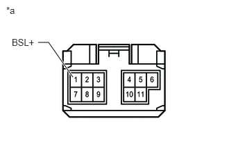
E410122C04
0.573,0.635 0.729,0.635 0.729,0.635 1.094,1.156 true 0.177,0.552 0.677,0.75 0.5,0.198 10 false BSL+ 0.094,0.073 0.406,0.271 0.313,0.198 10 false *a
*a Front view of outer mirror retractor LH
(to Vehicle Harness)


Disconnect the R20 outer rear view mirror assembly LH connector.


b.

Disconnect the IND1 outer mirror LH (outer rear view mirror indicator LH) connector.


c.

Measure the resistance according to the value(s) in the table below.

Standard Resistance:
Tester Connection Condition Always
1 (BSL+) - Body ground Always 10 kΩ or higher


Result:
Proceed to
OK
NG


OK

4.INSPECT OUTER MIRROR LH (OUTER REAR VIEW MIRROR INDICATOR LH)

NG

4.INSPECT OUTER MIRROR LH (OUTER REAR VIEW MIRROR INDICATOR LH)
a.

Remove the outer mirror LH (outer rear view mirror indicator LH).

Click hereVehicle Exterior>MIRROR (EXT)>OUTER REAR VIEW MIRROR GLASS>REMOVAL


b.

Result:
Proceed to
OK
NG


OK

NG

5.CHECK HARNESS AND CONNECTOR (BLIND SPOT MONITOR SENSOR LH - OUTER REAR VIEW MIRROR ASSEMBLY LH)
a.
E406932C16
1.5,0.25 1.906,0.552 0.406,0.302 1.875,1.146 2.385,0.51 2.385,0.51 2.583,0.51 true 0.083,0.052 0.396,0.25 0.313,0.198 10 false *a 1.563,0.323 1.875,0.521 0.313,0.198 10 false e2 2.667,0.427 3.073,0.615 0.406,0.188 10 false OMIL
*a Front view of wire harness connector
(to Blind Spot Monitor Sensor LH)


Disconnect the blind spot monitor sensor LH connector.


b.

Disconnect the R23 outer rear view mirror assembly LH connector.


c.

Measure the resistance according to the value(s) in the table below.

Standard Resistance:
Tester Connection Condition Always
e2-4 (OMIL) - Body ground Always 10 kΩ or higher


Result:
Proceed to
OK
NG


OK

6.INSPECT OUTER REAR VIEW MIRROR ASSEMBLY LH

NG

REPAIR OR REPLACE HARNESS OR CONNECTOR

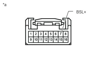
6.INSPECT OUTER REAR VIEW MIRROR ASSEMBLY LH
a.
E395851C17
2.104,1.115 2.354,0.385 2.354,0.385 2.51,0.385 true 2.625,0.323 3.125,0.521 0.5,0.198 10 false BSL+ 0.094,0.073 0.406,0.271 0.313,0.198 10 false *a
*a Front view of outer rear view mirror assembly LH
(to Vehicle Harness)


Disconnect the R23 outer rear view mirror assembly LH connector.


b.

Disconnect the IND1 outer mirror LH (outer rear view mirror indicator LH) connector.


c.

Measure the resistance according to the value(s) in the table below.

Standard Resistance:
Tester Connection Condition Always
7 (BSL+) - Body ground Always 10 kΩ or higher


Result:
Proceed to
OK
NG


OK

7.INSPECT OUTER MIRROR LH (OUTER REAR VIEW MIRROR INDICATOR LH)

NG

7.INSPECT OUTER MIRROR LH (OUTER REAR VIEW MIRROR INDICATOR LH)
a.

Remove the outer mirror LH (outer rear view mirror indicator LH).

Click hereVehicle Exterior>MIRROR (EXT)>OUTER REAR VIEW MIRROR GLASS>REMOVAL


b.

Result:
Proceed to
OK
NG


OK

NG