MIRROR (EXT) OUTER REAR VIEW MIRROR GLASS INSPECTION
PROCEDURE

 87961
1.INSPECT OUTER MIRROR LH (w/ Blind Spot Monitor System)
87961
1.INSPECT OUTER MIRROR LH (w/ Blind Spot Monitor System)
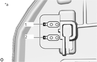
| *a | Component without harness connected
(Outer Mirror LH) |
Check the outer mirror heater operation.
Measure the resistance according to the value(s) in the table below.
- Standard Resistance:
Tester Connection Condition Specified Condition 1 - 2 25°C (77°F) 7.2 to 9.3 Ω
If the result is not as specified, replace the outer mirror LH.
Check the outer rear view mirror indicator operation.
Connect 4 new 1.5 V dry-cell batteries in series.
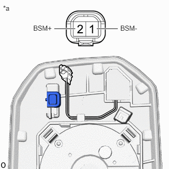
| *a | Component without harness connected
(Outer Mirror LH) |
Apply 6 V dry-cell batteries to the terminals of the connector, and check the blind spot monitor indicator condition.
- NOTICE:
- ·
Do not use rechargeable batteries as they may not output a voltage of 1.5 V.
·Do not apply a voltage of more than 6 V.
- OK:
Battery Connection Specified Condition Positive (+) end of the 6 V dry-cell battery → 2 (BSM+)
Negative (-) end of the 6 V dry-cell battery → 1 (BSM-)Outer rear view mirror indicator comes on
If the result is not as specified, replace the outer mirror LH.
87931
2.INSPECT OUTER MIRROR RH (w/ Blind Spot Monitor System)
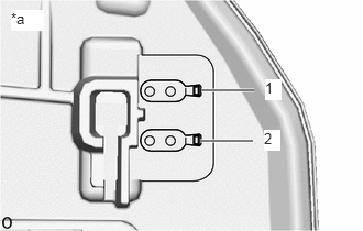
| *a | Component without harness connected
(Outer Mirror RH) |
Check the outer mirror heater operation.
Measure the resistance according to the value(s) in the table below.
- Standard Resistance:
Tester Connection Condition Specified Condition 1 - 2 25°C (77°F) 7.2 to 9.3 Ω
If the result is not as specified, replace the outer mirror RH.
Check the outer rear view mirror indicator operation.
Connect 4 new 1.5 V dry-cell batteries in series.
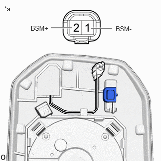
| *a | Component without harness connected
(Outer Mirror RH) |
Apply 6 V dry-cell batteries to the terminals of the connector, and check the blind spot monitor indicator condition.
- NOTICE:
- ·
Do not use rechargeable batteries as they may not output a voltage of 1.5 V.
·Do not apply a voltage of more than 6 V.
- OK:
Battery Connection Specified Condition Positive (+) end of the 6 V dry-cell battery → 2 (BSM+)
Negative (-) end of the 6 V dry-cell battery → 1 (BSM-)Outer rear view mirror indicator comes on
If the result is not as specified, replace the outer mirror RH.