DOOR LOCK DOOR LOCK JUNCTION INSTALLATION
CAUTION / NOTICE / HINT
- HINT:
- ·
Use the same procedure for RHD and LHD vehicles.
·The procedure listed below is for LHD vehicles.
·Use the same procedure for the RH and LH sides.
·Use the same procedure described for the RH side.
·A bolt without a torque specification is shown in the standard bolt chart.
PROCEDURE

 84262B
1.INSTALL SLIDE DOOR CONTROL JUNCTION FEMALE
84262B
1.INSTALL SLIDE DOOR CONTROL JUNCTION FEMALE
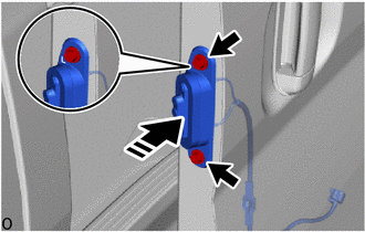

|
Install in this Direction |
for LH Side:
Install the slide door control junction female with the 2 bolts as shown in the illustration.
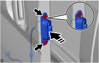
|
|
Install in this Direction |
for RH Side:
Install the slide door control junction female with the 2 bolts as shown in the illustration.
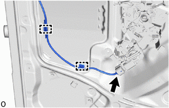
Connect the connector and attach the clamp.
67851E
2.INSTALL SLIDE DOOR SERVICE HOLE COVER RH
67603
3.INSTALL REAR DOOR TRIM BOARD SUB-ASSEMBLY RH (for Semi-trim, for Type A)
67603
4.INSTALL REAR DOOR TRIM BOARD SUB-ASSEMBLY RH (for Semi-trim, for Type B)
67680B
5.INSTALL SLIDE DOOR TRIM BOARD ASSEMBLY RH (for Full-trim, for Standard Roof)
67680B
6.INSTALL SLIDE DOOR TRIM BOARD ASSEMBLY RH (for Full-trim, for High Roof)
67667A
7.INSTALL SLIDE DOOR WINDOW GARNISH RH (for Full-trim, for Standard Roof)
67667A
8.INSTALL SLIDE DOOR WINDOW GARNISH RH (for Full-trim, for High Roof)
84261B
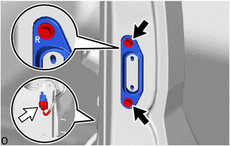
9.INSTALL SLIDE DOOR CONTROL JUNCTION MALE
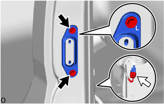

|
Bolt |

|
Connector |
for LH Side:
Install the slide door control junction male with the 2 bolts as shown in the illustration.
Connect the connector.
|
|
Bolt |
|
|
Connector |
for RH Side:
Install the slide door control junction male with the 2 bolts as shown in the illustration.
Connect the connector.
73210
10.INSTALL FRONT SEAT OUTER BELT ASSEMBLY RH
- HINT:
-
Use the same procedure described for the LH side.
11.CONNECT CABLE TO NEGATIVE BATTERY TERMINAL (w/ Pretensioner and Force Limiter)
12. INITIALIZATION AFTER RECONNECTING BATTERY TERMINAL
- HINT:
-
When disconnecting and reconnecting the battery, there is an automatic learning function that completes learning when the respective system is used.
13. PERFORM DIAGNOSTIC SYSTEM CHECK (w/ Pretensioner and Force Limiter)
14.CHECK SRS WARNING LIGHT (w/ Pretensioner and Force Limiter)
15.INSPECT SEAT BELT WARNING SYSTEM (w/ Seat Belt Warning System)