THEFT DETERRENT / KEYLESS ENTRY THEFT DETERRENT SYSTEM TERMINALS OF ECU
CHECK MAIN BODY ECU (MULTIPLEX NETWORK BODY ECU) AND INSTRUMENT PANEL JUNCTION BLOCK ASSEMBLY
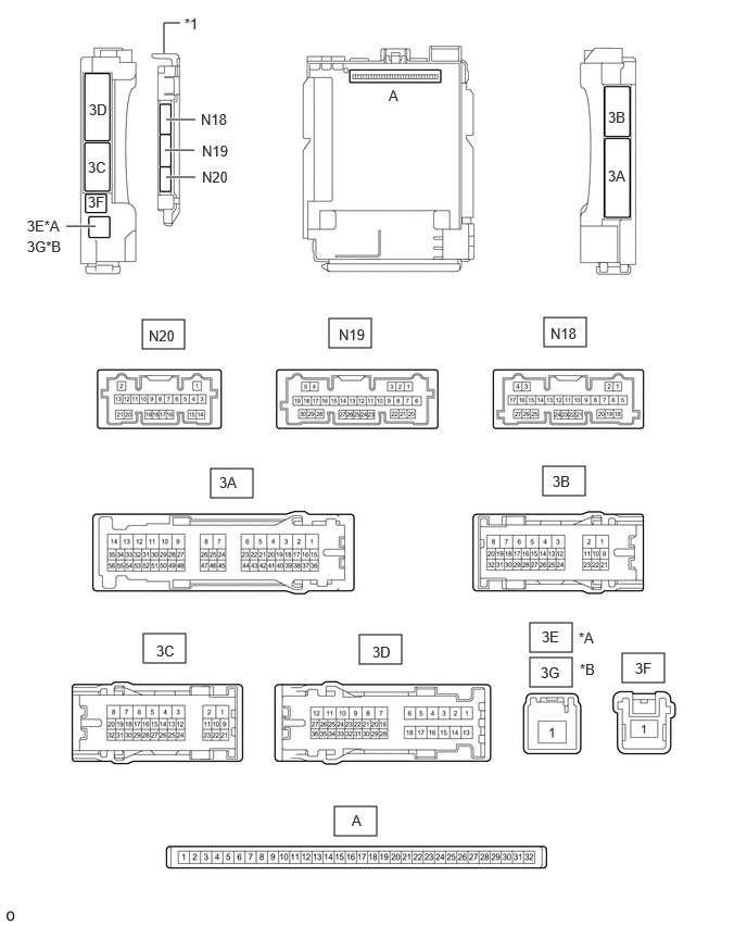
| *A | for LHD | *B | for RHD |
| *1 | Main Body ECU (Multiplex Network Body ECU) | - | - |
Remove the main body ECU (multiplex network body ECU) from the instrument panel junction block assembly.
for LHD:
for RHD:
Connect the instrument panel junction block assembly connectors.
Measure the voltage and resistance according to the value(s) in the table below.
| Tester Connection | Wiring Color | Terminal Description | Condition | Specified Condition |
|---|---|---|---|---|
| A-11 (GND1) - Body ground | None - Body ground | Ground | Always | Below 1 Ω |
| A-30 (ACC) - Body ground | None - Body ground | ACC power supply | Ignition switch ACC | 11 to 14 V |
| Ignition switch off | Below 1 V | |||
| A-31 (BECU) - Body ground | None - Body ground | Battery power supply | Always | 11 to 14 V |
| A-32 (IG) - Body ground | None - Body ground | IG power supply | Ignition switch ON | 11 to 14 V*1
10.5 to 16 V*2 |
| Ignition switch off | Below 1 V | |||
| N19-1 (FLCY) - Body ground | R - Body ground | Front door courtesy light switch assembly LH input signal | Front door LH closed (OFF) → open (ON) | 10 kΩ or higher → Below 1 Ω |
| N19-6 (FRCY) - Body ground | R - Body ground | Front door courtesy light switch assembly RH input signal | Front door RH closed (OFF) → open (ON) | 10 kΩ or higher → Below 1 Ω |
| A-13 (LCTY) - Body ground*3 | None - Body ground | Rear door courtesy light switch assembly LH input signal | Slide door LH closed (OFF) → open (ON) | 10 kΩ or higher → Below 1 Ω |
| A-2 (RCTY) - Body ground*4 | None - Body ground | Rear door courtesy light switch assembly RH input signal | Slide door RH closed (OFF) → open (ON) | 10 kΩ or higher → Below 1 Ω |
| A-4 (BCTY) - Body ground | None - Body ground | Back door courtesy light switch signal | Back door closed (OFF) → open (ON) | 10 kΩ or higher → Below 1 Ω |
| N19-30 (HCTY) - Body ground | LG - Body ground | Engine hood courtesy switch input signal | Engine hood open (OFF) → closed (ON) | 10 kΩ or higher → Below 1 Ω |
| A-3 (KSW) - Body ground*5 | None - Body ground | Unlock warning switch input | Key not in key cylinder (OFF) → Key in key cylinder (ON) | 10 kΩ or higher → Below 1 Ω |
*1: w/o Stop and Start System
*2: w/ Stop and Start System
*3: w/ Slide Door LH
*4: w/ Slide Door RH
*5: w/o Entry and Start System
Install the main body ECU (multiplex network body ECU) to the instrument panel junction block assembly.
for LHD:
for RHD:
Measure the voltage and check for pulses according to the value(s) in the table below.
| Tester Connection | Wiring Color | Terminal Description | Condition | Specified Condition |
|---|---|---|---|---|
| 3B-13 (LSFL) - Body ground | B - Body ground | Front door LH unlock detection switch input signal | Front door LH unlocked | Below 1 V |
| Ignition switch off, all doors closed and front door LH locked | Pulse generation | |||
| 3B-12 (LSFR) - Body ground | B - Body ground | Front door RH unlock detection switch input signal | Front door RH unlocked | Below 1 V |
| Ignition switch off, all doors closed and front door RH locked | Pulse generation | |||
| 3B-14 (LSWL) - Body ground*1 | L - Body ground | Slide door LH unlock detection switch input signal | Slide door LH unlocked | Below 1 V |
| Ignition switch off, all doors closed and slide door LH locked | Pulse generation | |||
| N18-20 (LSWR) - Body ground*2 | L - Body ground | Slide door RH unlock detection switch input signal | Slide door RH unlocked | Below 1 V |
| Ignition switch off, all doors closed and slide door RH locked | Pulse generation | |||
| N19-27 (LSWB) - Body ground | GR - Body ground | Back door unlock detection switch input signal | Back door unlocked | Below 1 V |
| Ignition switch off, all doors closed and back door locked | Pulse generation | |||
| N20-18 (L2) - Body ground | W - Body ground | Driver door or front passenger door*3 key-linked lock input | Driver door or front passenger door*3 key cylinder turned to lock position | Below 1 V |
| Driver door and front passenger door*3 key cylinder off | Pulse generation | |||
| N20-19 (UL2) - Body ground*3 | Y - Body ground | Front passenger door key-linked unlock input | Front passenger door key cylinder turned to unlock position | Below 1 V |
| Front passenger door key cylinder off | Pulse generation | |||
| N20-17 (UL3) - Body ground | Y - Body ground | Driver door key-linked unlock input | Driver door key cylinder turned to unlock position | Below 1 V |
| Driver door key cylinder off | Pulse generation | |||
| N19-7 (IND) - Body ground*4 | GR - Body ground | Security indicator light illumination | Security indicator light off | Below 2 V |
| Security indicator light blinking | Pulse generation | |||
| 3C-26 (SH) - Body ground*5 | BE - Body ground | Security horn drive | Security horn sounding (Theft deterrent system is in alarm sounding state) | Pulse generation (Below 1 V ←→ 11 to 14 V) |
| N20-12 (SSCL) - Body ground*6 | P - Body ground | Theft warning siren assembly drive | Theft warning siren assembly sounding (Theft deterrent system is in alarm sounding state) | Pulse generation (Below 1 V ←→ 11 to 14 V) |
| 3C-27 (HORN) - Body ground | G - Body ground | Vehicle horn drive | Vehicle horns sounding (Theft deterrent system is in alarm sounding state) | Pulse generation (Below 1 V ←→ 11 to 14 V) |
*1: w/ Slide Door LH
*2: w/ Slide Door RH
*3: w/ Front Passenger Door Key Cylinder
*4: w/o Entry and Start System
*5: w/ Security Horn Assembly
*6: w/o Security Horn Assembly
CHECK COMBINATION METER ASSEMBLY
CHECK CERTIFICATION ECU (SMART KEY ECU ASSEMBLY) (w/ Entry and Start System)