POWER DISTRIBUTION MAIN BODY ECU(for LHD) INSTALLATION
CAUTION / NOTICE / HINT
- NOTICE:
-
When installing the main body ECU (multiplex network body ECU), always replace it with a new one.
- w/ Entry and Start System:
Before replacing the main body ECU (multiplex network body ECU), refer to Service Bulletin.
- HINT:
-
A bolt without a torque specification is shown in the standard bolt chart.
PROCEDURE

 1.INSTALL MAIN BODY ECU (MULTIPLEX NETWORK BODY ECU)
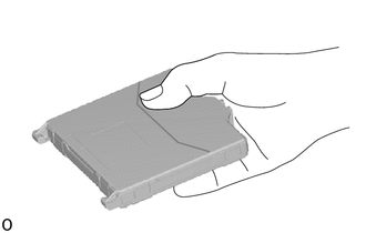
Hold the main body ECU (multiplex network body ECU) with your dominant hand.
- NOTICE:
-
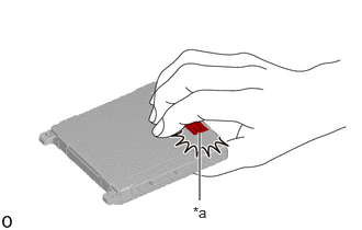 1.896,1.906 1.896,1.26 true 1.833,1.938 2.146,2.094 0.313,0.156 10 false *a
*a Connector
- ·
Do not touch the connector.
·Make sure foreign matter does not enter the terminals.
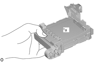
| *a | Fitting Surface |
Hold the instrument panel junction block assembly with your other hand.
- NOTICE:
-
Make sure there is no foreign matter in the fitting surface.
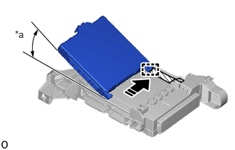
| *a | 20° or more |

|
Install in this Direction |

|
Housing Sidewall |
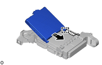
Set the guide of the main body ECU (multiplex network body ECU) against the housing sidewall.
- HINT:
-
Make sure the angle between the instrument panel junction block assembly and the main body ECU (multiplex network body ECU) is 20° or more.
|
|
Install in this Direction |
|
|
Housing Sidewall |
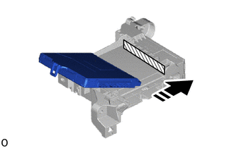
Slide the guide of the main body ECU (multiplex network body ECU) along the housing sidewall in the direction indicated by the arrow.
|
|
Install in this Direction |
|
|
Side A |
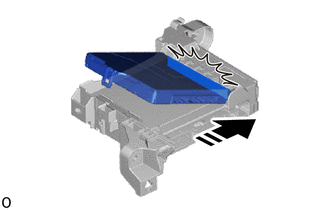
Slide it until it contacts side A.
|
|
Install in this Direction |
Contact side A.
- NOTICE:
-
Do not contact side A with the main body ECU (multiplex network body ECU) too hard.
| *a | Center of Rotation (Contacts Surface A) |
|
|
Rotate in this Direction |
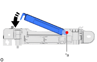
| *a | Center of Rotation (Contacts Surface A) |
|
|
Rotate in this Direction |
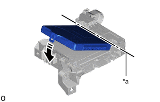
While pressing the main body ECU (multiplex network body ECU) against side A (center of rotation) of the instrument panel junction block assembly, rotate it until it enters the lock of the instrument panel junction block assembly.
- HINT:
-
The center of rotation is the one that contacts surface A.
Rotate it until it enters the lock of the instrument panel junction block assembly.
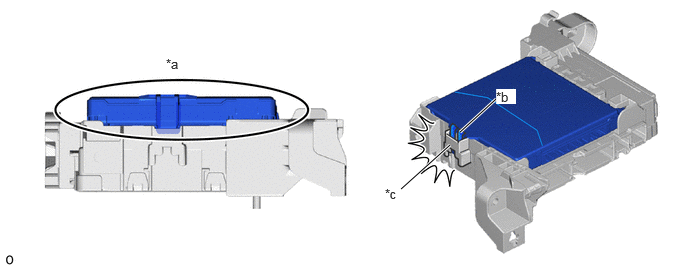
| *a | Before Locking | *b | Main Body ECU (Multiplex Network Body ECU) Lock |
| *c | Instrument Panel Junction Block Assembly Lock | - | - |
|
|
Install in this Direction |
|
|
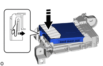
Pressing Area |
Press the pressing area of the main body ECU (multiplex network body ECU).
- NOTICE:
- ·
Press it in one of the following ways.
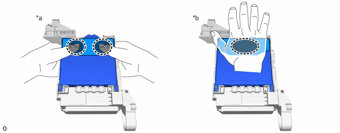 0.76,0.292 1.073,0.448 0.313,0.156 10 false *a 4.063,0.292 4.375,0.448 0.313,0.156 10 false *b
*a Press the 2 sides of the main body ECU (multiplex network body ECU) with both hands. *b Press the center of the main body ECU (multiplex network body ECU) with one hand. 
Place fingers or the palm of your hand here - -
·Do not hit on or put your weight on the main body ECU (multiplex network body ECU) when engaging the main body ECU (multiplex network body ECU).
·Check the engagement of the main body ECU (multiplex network body ECU) and the instrument panel junction block assembly by the locking sound.
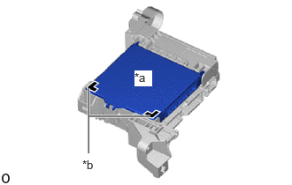
| *a | Back Side of Main Body ECU (Multiplex Network Body ECU) |
| *b | Rib Surrounding Instrument Panel Junction Block Assembly |
Check that the back side of the main body ECU (multiplex network body ECU) and the rib surrounding the instrument panel junction block assembly are the same height.
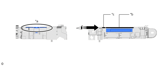
| *a | After Locking (Height Matches) | *b | Back Side of Main Body ECU (Multiplex Network Body ECU) |
| *c | Rib Surrounding Instrument Panel Junction Block Assembly | - | - |
|
|
Confirm Visually | - | - |
2.INSTALL INSTRUMENT PANEL JUNCTION BLOCK ASSEMBLY WITH MAIN BODY ECU (for Manual Transmission)
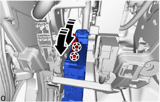
|
|
Rotate in this Direction |
Attach the claw to connect the 2 lever connectors.
- NOTICE:
-
Be sure to connect the connector securely.
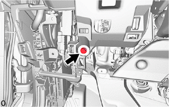
Install the bolt.
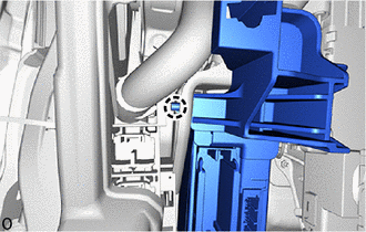
Attach the claw and install the instrument panel junction block assembly with main body ECU to the wiring harness clamp bracket.
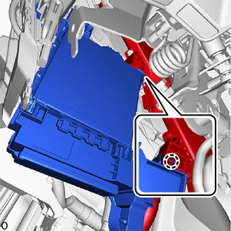
Attach the claw and install the wiring harness protector assembly to the instrument panel junction block assembly with main body ECU.
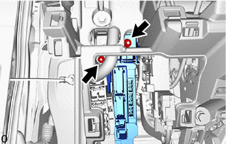
Install the instrument panel junction block assembly with main body ECU together with the wiring harness clamp bracket with the 2 nuts.
- Torque:
- 12.5 N*m (127 kgf*cm, 9 ft.*lbf)
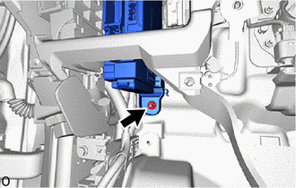
Install the nut.
- Torque:
- 12.5 N*m (127 kgf*cm, 9 ft.*lbf)
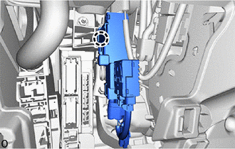
Attach the claw and install the wiring harness protector to the instrument panel junction block assembly with main body ECU.
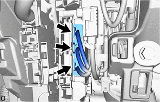
Connect the 3 connectors.
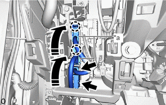
| *a | Lever Connector |
|
|
Rotate in this Direction |
Connect the 2 connectors.
Attach the claw to connect the 2 lever connectors.
- NOTICE:
-
Be sure to connect the connector securely.
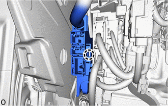
Attach the claw and install the connector holder to the instrument panel junction block assembly with main body ECU.
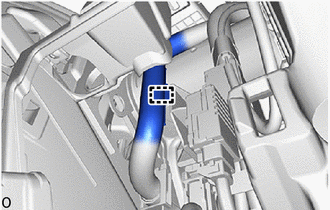
Attach the wire harness clamp.
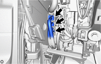
Connect the 3 connectors.
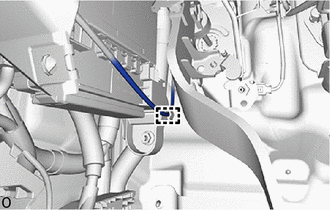
Attach the hood look control cable assembly to the guide.
3.INSTALL INSTRUMENT PANEL JUNCTION BLOCK ASSEMBLY WITH MAIN BODY ECU (for Automatic Transmission)
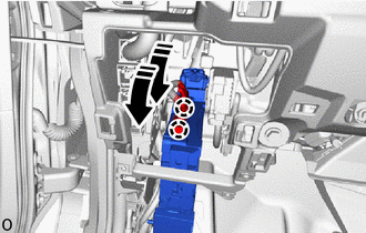
|
|
Rotate in this Direction |
Attach the claw to connect the 2 lever connectors.
- NOTICE:
-
Be sure to connect the connector securely.
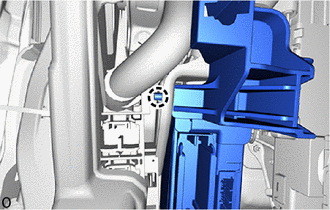
Attach the claw to install the instrument panel junction block assembly with main body ECU to the wiring harness clamp bracket.
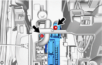
Install the instrument panel junction block assembly with main body ECU together with the wiring harness clamp bracket with the 2 nuts.
- Torque:
- 12.5 N*m (127 kgf*cm, 9 ft.*lbf)
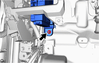
Install the nut.
- Torque:
- 12.5 N*m (127 kgf*cm, 9 ft.*lbf)
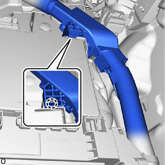
Attach the claw and install the wiring harness protector to the instrument panel junction block assembly with main body ECU.
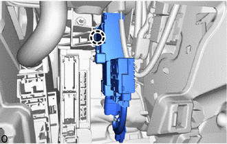
Attach the claw and install the wiring harness protector to the instrument panel junction block assembly with main body ECU.
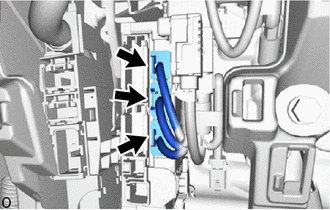
Attach the 3 connectors.
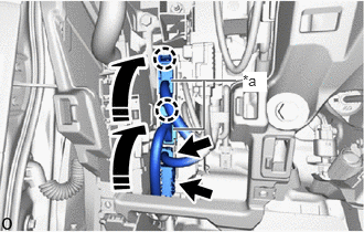
| *a | Lever Connector |
|
|
Rotate in this Direction |
Connect the 2 connectors.
Attach the claw to connect the 2 lever connectors.
- NOTICE:
-
Be sure to connect the connector securely.
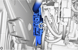
Attach the claw and install the connector holder to the instrument panel junction block assembly with main body ECU.
Attach the wire harness clamp.
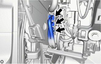
Connect the 3 connectors.
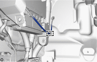
Attach the hood look control cable assembly to the guide.
73900
4.INSTALL LOWER NO. 1 INSTRUMENT PANEL AIRBAG ASSEMBLY (w/ Knee Airbag)
55313
5.INSTALL LOWER INSTRUMENT PANEL LH (w/o Knee Airbag)
55445B
6.INSTALL INSTRUMENT PANEL FINISH PLATE (w/o Knee Airbag)
55433B
7.INSTALL LOWER NO. 2 INSTRUMENT PANEL FINISH PANEL
55044C
8.INSTALL INSTRUMENT PANEL FINISH PANEL SUB-ASSEMBLY
55432D
9.INSTALL LOWER NO. 1 INSTRUMENT PANEL FINISH PANEL
77306
10.INSTALL FUEL LID LOCK OPEN LEVER SUB-ASSEMBLY
53601
11.INSTALL HOOD LOCK CONTROL LEVER SUB-ASSEMBLY
55641
12.INSTALL NO. 1 INSTRUMENT PANEL UNDER COVER
55318C
13.INSTALL INSTRUMENT SIDE PANEL LH
55011A
14.INSTALL NO. 1 INSTRUMENT PANEL GARNISH SUB-ASSEMBLY
55631A
15.INSTALL NO. 1 INSTRUMENT PANEL UNDER TRAY STOPPER
62112
16.INSTALL COWL SIDE TRIM BOARD LH
67914B
17.INSTALL FRONT DOOR SCUFF PLATE LH
67912A
18.INSTALL FRONT DOOR OUTSIDE SCUFF PLATE LH
19.CONNECT CABLE TO NEGATIVE BATTERY TERMINAL
20. INITIALIZATION AFTER RECONNECTING BATTERY TERMINAL
- HINT:
-
When disconnecting and reconnecting the battery, there is an automatic learning function that completes learning when the respective system is used.
21. PERFORM DIAGNOSTIC SYSTEM CHECK
22.CHECK SRS WARNING LIGHT