DOOR / HATCH SLIDE DOOR CLOSER SYSTEM Slide Door Closer RH does not Operate
DESCRIPTION
The slide door closer controls the slide door motor unit RH (slide door ECU RH), receives signals from each switch inside the power slide door lock assembly RH and drives the closer motor.
WIRING DIAGRAM

CAUTION / NOTICE / HINT
- NOTICE:
- ·
Inspect the fuses for circuits related to this system before performing the following inspection procedure.
·If the replacement, removal and installation of the slide door motor unit or disconnection of the connectors of the slide door motor unit has been performed, initialize the power slide door system.
PROCEDURE
Check that no foreign objects are stuck between the vehicle body and the slide door.
- OK:
Door can be fully closed.
- Result:
Proceed to OK NG
OK
NG
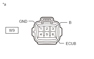
| *a | Front view of wire harness connector
(to Slide Door Motor Unit RH [Slide Door ECU RH]) |
Disconnect the slide door motor unit RH (slide door ECU RH) connector.
Measure the resistance according to the value(s) in the table below.
- Standard Resistance:
Tester Connection Condition Specified Condition W9-1 (GND) - Body ground Always Below 1 Ω
Measure the voltage according to the value(s) in the table below.
- Standard Voltage:
Tester Connection Condition Specified Condition W9-3 (B) - Body ground Always 11 to 14 V W9-6 (ECUB) - Body ground Always 11 to 14 V
- Result:
Proceed to OK NG
OK
NG
Perform the Active Test according to the display on the GTS.
- Body Electrical > Rear Right Door > Active Test
-
Tester Display Measurement Item Control Range Diagnostic Note PSD Open Slide door open ON or OFF -
- Body Electrical > Rear Right Door > Active Test
-
Tester Display PSD Open - 50004 161 14
- OK:
Slide door lock assembly RH (closer motor) operates.
- Result:
Proceed to OK NG
OK
NG
Read the Data List according to the display on the GTS.
- Body Electrical > Rear Right Door > Data List
-
Tester Display Measurement Item Normal Condition Reference Value Diagnostic Note Pawl Switch Status of the pawl switch ON or OFF ON: Pawl switch on
OFF: Pawl switch off- Half Switch Status of the half-latch switch ON or OFF ON: Half-latch switch on
OFF: Half-latch switch off- Full Switch Status of the full-latch switch ON or OFF ON: Full-latch switch on
OFF: Full-latch switch off- Neutral Position Close Switch Status of the neutral position close switch ON or OFF ON: Neutral position close switch on
OFF: Neutral position close switch off-
- Body Electrical > Rear Right Door > Data List
-
Tester Display Pawl Switch Half Switch Full Switch Neutral Position Close Switch - 50003 161 1,2,3,44
- OK:
The switches switch ON/OFF according to the slide door open/close operation.
- Result:
Proceed to OK NG
OK
NG
Read the Data List according to the display on the GTS.
- Body Electrical > Rear Right Door > Data List
-
Tester Display Measurement Item Normal Condition Reference Value Diagnostic Note Handle Switch1 Slide door lock remote control assembly RH (close switch) signal ON or OFF ON: Slide door inside handle or outside handle close operation performed (slide door lock remote control assembly RH [close switch] on)
OFF: Slide door inside handle or outside handle operation not performed or open operation performed (slide door lock remote control assembly RH [close switch] off)- Handle Switch2 Slide door lock remote control assembly RH (open switch) signal ON or OFF ON: Slide door inside handle or outside handle open operation performed (slide door lock remote control assembly RH [open switch] on)
OFF: Slide door inside handle or outside handle operation not performed or close operation performed (slide door lock remote control assembly RH [open switch] off)-
- Body Electrical > Rear Right Door > Data List
-
Tester Display Handle Switch1 Handle Switch2 - 50003 161 6,7
- OK:
On the GTS screen, ON or OFF is displayed accordingly.
- Result:
Proceed to OK NG
OK
NG
Remove the slide door lock remote control assembly RH.
Inspect the slide door lock remote control assembly RH.
- Result:
Result Proceed to OK A NG (except Wagon) B NG (for Wagon) C
A
B
C
Disconnect the U3 slide door lock remote control assembly RH connector.
Disconnect the S4 slide door motor unit RH (slide door ECU RH) connector.
Measure the resistance according to the value(s) in the table below.
- Standard Resistance:
Tester Connection Condition Specified Condition U3-1 (DS1) - S4-8 (DS1) Always Below 1 Ω U3-2 (DS2) - S4-7 (DS2) Always Below 1 Ω U3-3 (GND) - Body ground Always Below 1 Ω U3-1 (DS1) or S4-8 (DS1) - Body ground Always 10 kΩ or higher U3-2 (DS2) or S4-7 (DS2) - Body ground Always 10 kΩ or higher
- Result:
Proceed to OK NG
OK
NG
Remove the power slide door lock assembly RH.
Inspect the power slide door lock assembly RH.
- Result:
Result Proceed to OK A NG (except Wagon) B NG (for Wagon) C
A
B
C
Disconnect the S3 power slide door lock assembly RH connector.
Disconnect the S4 slide door motor unit RH (slide door ECU RH) connector.
Measure the resistance according to the value(s) in the table below.
- Standard Resistance:
Tester Connection Condition Specified Condition S3-6 (FUL) - S4-9 (FUL) Always Below 1 Ω S3-5 (HAF) - S4-5 (HAF) Always Below 1 Ω S3-10 (POL) - S4-3 (POL) Always Below 1 Ω S3-9 (NPC) - S4-4 (P) Always Below 1 Ω S3-7 (E1) - Body ground Always Below 1 Ω S3-8 (NPR) - S4-1 (SPD) Always Below 1 Ω S3-6 (FUL) or S4-9 (FUL) - Body ground Always 10 kΩ or higher S3-5 (HAF) or S4-5 (HAF) - Body ground Always 10 kΩ or higher S3-10 (POL) or S4-3 (POL) - Body ground Always 10 kΩ or higher S3-9 (NPC) or S4-4 (P) - Body ground Always 10 kΩ or higher S3-8 (NPR) or S4-1 (SPD) - Body ground Always 10 kΩ or higher
- Result:
Proceed to OK NG
OK
NG
Remove the power slide door lock assembly RH.
Inspect the power slide door lock assembly RH.
- Result:
Result Proceed to OK A NG (except Wagon) B NG (for Wagon) C
A
B
C
Disconnect the S3 power slide door lock assembly RH connector.
Disconnect the S5 slide door motor unit RH (slide door ECU RH) connector.
Measure the resistance according to the value(s) in the table below.
- Standard Resistance:
Tester Connection Condition Specified Condition S3-1 (ACT+) - S5-2 (DC+) Always Below 1 Ω S3-4 (ACT-) - S5-1 (DC-) Always Below 1 Ω S3-1 (ACT+) or S5-2 (DC+) - Body ground Always 10 kΩ or higher S3-4 (ACT-) or S5-1 (DC-) - Body ground Always 10 kΩ or higher
- Result:
Proceed to OK NG
OK
NG