DOOR / HATCH POWER SLIDE DOOR MOTOR REMOVAL
CAUTION / NOTICE / HINT
The necessary procedures (adjustment, calibration, initialization, or registration) that must be performed after parts are removed and installed, or replaced during slide door motor unit removal/installation are shown below.
| Replaced Part or Performed Procedure | Effect/Inoperative Function when Necessary Procedure not Performed | Necessary Procedure | Link |
|---|---|---|---|
| Removal and installation of battery terminal | Parking assist monitor system | Memorize steering angle neutral point | ( 201902,999999,_56,_079315,_0385736,RM100000001GNRA,) 201902,999999,_56,_079315,_0385736,RM100000001GNRA,)
|
| Panoramic view monitor system | (201906,999999,_56,_079315,_0396274,RM100000001IGR3,)
|
||
| Slide door motor unit | Reset slide door close position | Power slide door system | (201902,999999,_59,_078503,_0381017,RM100000001FWXM,)
|
- HINT:
-
When the cable is disconnected / reconnected to the battery terminal, systems temporarily stop operating. However, each system has a function that completes learning the first time the system is used.
- ·
Learning completes when vehicle is driven
Effect/Inoperative Function When Necessary Procedures are not Performed Necessary Procedures Link *: w/ Stop and start system
Stop and start system* Drive the vehicle until stop and start control is permitted (approximately 5 to 60 minutes). ( 201902,999999,_51,_078825,_0382334,RM100000001GBQ1,)
Lane control system Drive the vehicle straight ahead at 15 km/h (10 mph) or more for 1 second or more. ( 201902,999999,_58,_078886,_0382740,RM100000001G6XB,)
Pre-collision system
·Learning completes when vehicle is operated normally
Effect/Inoperative Function When Necessary Procedures are not Performed Necessary Procedures Link Power slide door system Fully close the slide door by hand.
- HINT:
-
Initialization is not necessary if the above procedures are performed while the slide door is closed.
( 201902,999999,_59,_078503,_0381017,RM100000001FWXM,)
Air conditioning system After the ignition switch is turned to ON, the servo motor standard position is recognized. -
·Use the same procedure for RHD and LHD vehicles.
·The procedure listed below is for LHD vehicles.
·Use the same procedure for the RH and LH sides.
·Use the same procedure described for the RH side.
PROCEDURE

 1. PRECAUTION (w/ Rear Curtain Shield Airbag)
- CAUTION:
-
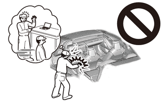
-
Be sure to read Precaution thoroughly before servicing.
- ·
- NOTICE:
-
After turning the ignition switch off, waiting time may be required before disconnecting the cable from the negative (-) battery terminal.
2.DISCONNECT CABLE FROM NEGATIVE BATTERY TERMINAL (w/ Rear Curtain Shield Airbag)
- CAUTION:
-
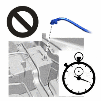
- ·
Wait at least 90 seconds after disconnecting the cable from the negative (-) battery terminal to disable the SRS system.
·If the airbag deploys for any reason, it may cause a serious accident.
74733
3.REMOVE NO. 1 HAND GRIP COVER (for RHD, w/ Hand Rail)
74708
4.REMOVE NO. 2 HAND GRIP FRAME SUB-ASSEMBLY (for RHD, w/ Hand Rail)
67917C
5.REMOVE REAR DOOR SCUFF PLATE RH
68394A
6.REMOVE SLIDE DOOR LOWER RAIL PLATE RH
7. SEPARATE SLIDE DOOR ASSEMBLY RH
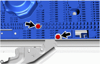
Move the slide door RH so that the 2 bolts are visible as shown in the illustration.
Remove the 2 bolts and disconnect the roller part of the lower slide door roller arm RH from the slide door motor unit RH.
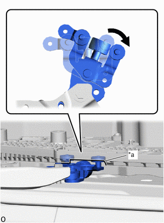
| *a | Cutout |
Rotate the roller part of the slide door lower roller arm sub-assembly RH clockwise to disconnect the slide door lower roller arm sub-assembly RH from the cutout of the rear floor step assembly RH.
- NOTICE:
- ·
Support the lower portion of the slide door RH when disconnecting the slide door lower roller arm sub-assembly RH, as the slide door RH becomes unstable.
·Work with 2 or more persons when disconnecting the slide door RH in order to prevent deformation and damage.
51078D
8.REMOVE SIDE STEP BRACKET SUB-ASSEMBLY RH (for Standard Roof)
51078D
9.REMOVE SIDE STEP BRACKET SUB-ASSEMBLY RH (for High Roof)
51079F
10.REMOVE SIDE STEP BRACKET SUB-ASSEMBLY LH (for Hand Rail)
85005A
11.REMOVE SLIDE DOOR MOTOR UNIT RH
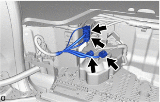
Disconnect the 4 connectors.
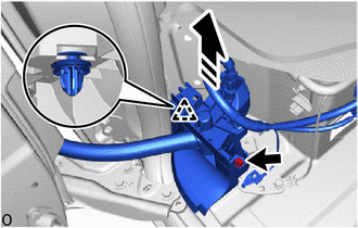

|
Remove in this Direction |
Disconnect the wire harness protector.
Remove the bolt.
Detach the clip and disconnect the wire harness protector as shown in the illustration.
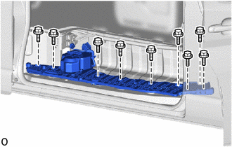
for Standard Roof:
Remove the 9 bolts and slide door motor unit RH.
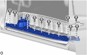
for High Roof:
Remove the 11 bolts and slide door motor unit RH.