DOOR LOCK SLIDE DOOR LOCK(except Wagon) INSPECTION
PROCEDURE

 69640C
1.INSPECT SLIDE DOOR LOCK REMOTE CONTROL ASSEMBLY LH
69640C
1.INSPECT SLIDE DOOR LOCK REMOTE CONTROL ASSEMBLY LH
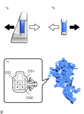
| *a | for Inside Handle |
| *b | for Outside Handle |
| *c | Component without harness connected
(Slide Door Lock Remote Control Assembly LH) |

|
Open |

|
Close |
Check the resistance of the slide door lock remote control assembly LH.
Measure the resistance according to the value(s) in the table below.
- Standard Resistance:
OPEN SWITCH (for Outside Handle) Tester Connection Condition Specified Condition 2 (DS2) - 3 (GND) Handle pulled (open side) Below 1 Ω Neutral position 10 kΩ or higher
OPEN SWITCH (for Inside Handle) Tester Connection Condition Specified Condition 2 (DS2) - 3 (GND) Handle pulled (open side) Below 1 Ω Neutral position 10 kΩ or higher
CLOSE SWITCH Tester Connection Condition Specified Condition 1 (DS1) - 3 (GND) Handle pulled (close side) Below 1 Ω Neutral position 10 kΩ or higher
If the result is not as specified, replace the slide door lock remote control assembly LH.
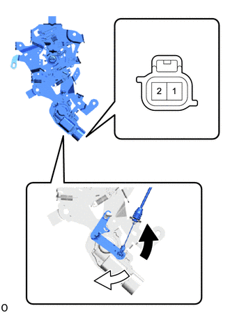
| *a | Component without harness connected
(Slide Door Lock Remote Control Assembly LH) |
|
|
Locked |
|
|
Unlocked |
Check the operation of the slide door lock remote control assembly LH (w/o position switch).
Apply battery voltage and check the operation of the door lock actuator.
- OK:
Battery Connection Specified Condition Battery positive (+) → Terminal 1 (OS)
Battery negative (-) → Terminal 2 (OSG)Locked Battery positive (+) → Terminal 2 (OSG)
Battery negative (-) → Terminal 1 (OS)Unlocked
If the result is not as specified, replace the slide door lock remote control assembly LH.
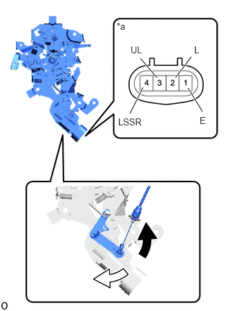
| *a | Component without harness connected
(Slide Door Lock Remote Control Assembly LH) |
|
|
Locked |
|
|
Unlocked |
Check the operation of the slide door lock remote control assembly LH (w/ position switch).
Apply battery voltage and check the operation of the door lock actuator.
- OK:
Battery Connection Specified Condition Battery positive (+) → Terminal 2 (L)
Battery negative (-) → Terminal 3 (UL)Locked Battery positive (+) → Terminal 3 (UL)
Battery negative (-) → Terminal 2 (L)Unlocked
If the result is not as specified, replace the slide door lock remote control assembly LH.
Measure the resistance according to the value(s) in the table below.
- Standard Resistance:
Tester Connection Condition Specified Condition 4 (LSSR) - 1 (E) Locked 10 kΩ or higher Unlocked Below 1 Ω
If the result is not as specified, replace the slide door lock remote control assembly LH.
69630C
2.INSPECT SLIDE DOOR LOCK REMOTE CONTROL ASSEMBLY RH
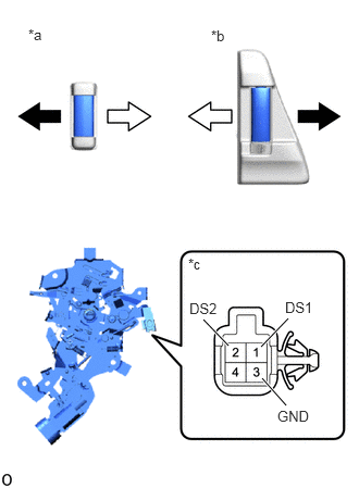
| *a | for Inside Handle |
| *b | for Outside Handle |
| *c | Component without harness connected
(Slide Door Lock Remote Control Assembly RH) |
|
|
Open |
|
|
Close |
Check the resistance of the slide door lock remote control assembly RH.
Measure the resistance according to the value(s) in the table below.
- Standard Resistance:
OPEN SWITCH (for Outside Handle) Tester Connection Condition Specified Condition 2 (DS2) - 3 (GND) Handle pulled (open side) Below 1 Ω Neutral position 10 kΩ or higher
OPEN SWITCH (for Inside Handle) Tester Connection Condition Specified Condition 2 (DS2) - 3 (GND) Handle pulled (open side) Below 1 Ω Neutral position 10 kΩ or higher
CLOSE SWITCH Tester Connection Condition Specified Condition 1 (DS1) - 3 (GND) Handle pulled (close side) Below 1 Ω Neutral position 10 kΩ or higher
If the result is not as specified, replace the slide door lock remote control assembly RH.
| *a | Component without harness connected
(Slide Door Lock Remote Control Assembly RH) |
|
|
Locked |
|
|
Unlocked |
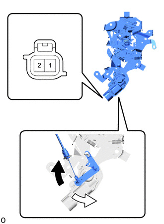
Check the operation of the slide door lock remote control assembly RH (w/o position switch).
Apply battery voltage and check the operation of the door lock actuator.
- OK:
Battery Connection Specified Condition Battery positive (+) → Terminal 1 (OS)
Battery negative (-) → Terminal 2 (OSG)Locked Battery positive (+) → Terminal 2 (OSG)
Battery negative (-) → Terminal 1 (OS)Unlocked
If the result is not as specified, replace the slide door lock remote control assembly RH.
| *a | Component without harness connected
(Slide Door Lock Remote Control Assembly RH) |
|
|
Locked |
|
|
Unlocked |
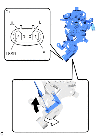
Check the operation of the slide door lock remote control assembly RH (w/ position switch).
Apply battery voltage and check the operation of the door lock actuator.
- OK:
Battery Connection Specified Condition Battery positive (+) → Terminal 2 (L)
Battery negative (-) → Terminal 3 (UL)Locked Battery positive (+) → Terminal 3 (UL)
Battery negative (-) → Terminal 2 (L)Unlocked
If the result is not as specified, replace the slide door lock remote control assembly RH.
Measure the resistance according to the value(s) in the table below.
- Standard Resistance:
Tester Connection Condition Specified Condition 4 (LSSR) - 1 (E) Locked 10 kΩ or higher Unlocked Below 1 Ω
If the result is not as specified, replace the slide door lock remote control assembly RH.
69300B
3.INSPECT POWER SLIDE DOOR LOCK ASSEMBLY LH (w/ Power Slide Door)
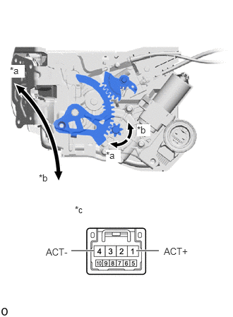
| *a | Direction Release Operation |
| *b | Direction Close Operation |
| *c | Component without harness connected
(Power Slide Door Lock Assembly LH) |
Check the operation of the door lock motor.
Apply battery voltage and check the operation of the door lock motor.
- OK:
Battery Connection Specified Condition Battery positive (+) → Terminal 1 (ACT+)
Battery negative (-) → Terminal 4 (ACT-)Close Operation Battery positive (+) → Terminal 4 (ACT-)
Battery negative (-) → Terminal 1 (ACT+)Release Operation
If the result is not as specified, replace the slide door lock assembly LH.
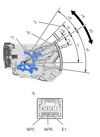
| *1 | Active lever |
| *a | Direction Release Operation |
| *b | Direction Close Operation |
| *c | Neutral position (Neutral Release Switch) |
| *d | Neutral position (Neutral Close Switch) |
| *e | 24.7° |
| *f | 12.8° |
| *g | 3° |
| *h | 39.9° |
| *i | 30.9° |
| *j | 10.2° |
| *k | Component without harness connected
(Slide door lock assembly LH) |

|
Neutral Release Switch ON Area |

|
Neutral Close Switch ON Area |
Check the resistance of the neutral switch.
Measure the resistance according to the value(s) in the table below.
- Standard Resistance:
NEUTRAL CLOSE SWITCH Tester Connection Condition Specified Condition 7 (E1) - 9 (NPC) Neutral position
(neutral release switch)10 kΩ or higher 7 (E1) - 9 (NPC) Neutral position
(neutral close switch)10 kΩ or higher 7 (E1) - 9 (NPC) Active lever is moved in direction of release operation 10 kΩ or higher 7 (E1) - 9 (NPC) Active lever is moved in direction of close operation Below 1 Ω
NEUTRAL RELEASE SWITCH Tester Connection Condition Specified Condition 7 (E1) - 8 (NPR) Neutral position
(neutral release switch)Below 1 Ω 7 (E1) - 8 (NPR) Neutral position
(neutral close switch)10 kΩ or higher 7 (E1) - 8 (NPR) Active lever is moved in direction of release operation Below 1 Ω 7 (E1) - 8 (NPR) Active lever is moved in direction of close operation 10 kΩ or higher
If the result is not as specified, replace the slide door lock assembly LH.
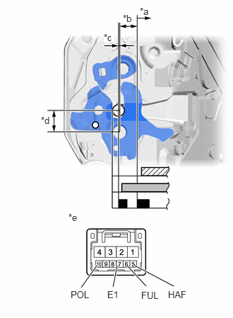
| *a | Open Latch |
| *b | Half-latch |
| *c | Full-latch |
| *d | 13.1 mm (0.516 in.) |
| *e | Component without harness connected
(Slide door lock assembly LH) |

|
Pole Switch ON Area |

|
Full-latch Switch ON Area |
|
|
Half-latch Switch ON Area |
Check the resistance of the latch switch and pole switch.
Measure the resistance according to the value(s) in the table below.
- Standard Resistance:
FULL LATCH SWITCH Tester Connection Condition Specified Condition 6 (FUL) - 7 (E1) Open-latch Below 1 Ω 6 (FUL) - 7 (E1) Half-latch 10 kΩ or higher 6 (FUL) - 7 (E1) Full-latch 10 kΩ or higher
HALF LATCH SWITCH Tester Connection Condition Specified Condition 5 (HAF) - 7 (E1) Open-latch Below 1 Ω 6 (FUL) - 7 (E1) Half-latch Below 1 Ω 6 (FUL) - 7 (E1) Full-latch 10 kΩ or higher
POLE SWITCH Tester Connection Condition Specified Condition 10 (POL) - 7 (E1) Open-latch Below 1 Ω 10 (POL) - 7 (E1) Half-latch 10 kΩ or higher 10 (POL) - 7 (E1) Between half-latch and full-latch 10 kΩ or higher → Below 1 Ω 10 (POL) - 7 (E1) Full-latch 10 kΩ or higher
If the result is not as specified, replace the slide door lock assembly LH.
69200
4.INSPECT POWER SLIDE DOOR LOCK ASSEMBLY RH (w/ Power Slide Door)
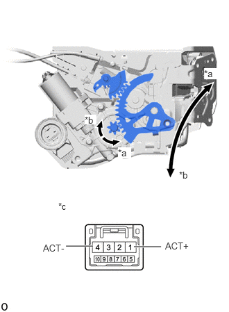
| *a | Direction Release Operation |
| *b | Direction Close Operation |
| *c | Component without harness connected
(Power Slide Door Lock Assembly RH) |
Check the operation of the door lock motor.
Apply battery voltage and check the operation of the door lock motor.
- OK:
Battery Connection Specified Condition Battery positive (+) → Terminal 1 (ACT+)
Battery negative (-) → Terminal 4 (ACT-)Close Operation Battery positive (+) → Terminal 4 (ACT-)
Battery negative (-) → Terminal 1 (ACT+)Release Operation
If the result is not as specified, replace the slide door lock assembly RH.
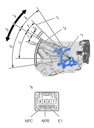
| *1 | Active lever |
| *a | Direction Release Operation |
| *b | Direction Close Operation |
| *c | Neutral position (Neutral Release Switch) |
| *d | Neutral position (Neutral Close Switch) |
| *e | 24.7° |
| *f | 12.8° |
| *g | 3° |
| *h | 39.9° |
| *i | 30.9° |
| *j | 10.2° |
| *k | Component without harness connected
(Slide door lock assembly RH) |
|
|
Neutral Release Switch ON Area |
|
|
Neutral Close Switch ON Area |
Check the resistance of the neutral switch.
Measure the resistance according to the value(s) in the table below.
- Standard Resistance:
NEUTRAL CLOSE SWITCH Tester Connection Condition Specified Condition 7 (E1) - 9 (NPC) Neutral position
(neutral release switch)10 kΩ or higher 7 (E1) - 9 (NPC) Neutral position
(neutral close switch)10 kΩ or higher 7 (E1) - 9 (NPC) Active lever is moved in direction of release operation 10 kΩ or higher 7 (E1) - 9 (NPC) Active lever is moved in direction of close operation Below 1 Ω
NEUTRAL RELEASE SWITCH Tester Connection Condition Specified Condition 7 (E1) - 8 (NPR) Neutral position
(neutral release switch)Below 1 Ω 7 (E1) - 8 (NPR) Neutral position
(neutral close switch)10 kΩ or higher 7 (E1) - 8 (NPR) Active lever is moved in direction of release operation Below 1 Ω 7 (E1) - 8 (NPR) Active lever is moved in direction of close operation 10 kΩ or higher
If the result is not as specified, replace the slide door lock assembly RH.
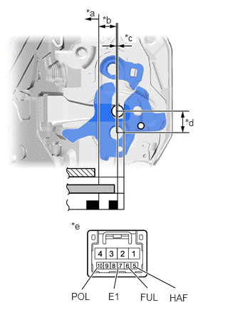
| *a | Open Latch |
| *b | Half-latch |
| *c | Full-latch |
| *d | 13.1 mm (0.516 in.) |
| *e | Component without harness connected
(Slide door lock assembly RH) |
|
|
Pole Switch ON Area |
|
|
Full-latch Switch ON Area |
|
|
Half-latch Switch ON Area |
Check the resistance of the latch switch and pole switch.
Measure the resistance according to the value(s) in the table below.
- Standard Resistance:
FULL LATCH SWITCH Tester Connection Condition Specified Condition 6 (FUL) - 7 (E1) Open-latch Below 1 Ω 6 (FUL) - 7 (E1) Half-latch 10 kΩ or higher 6 (FUL) - 7 (E1) Full-latch 10 kΩ or higher
HALF LATCH SWITCH Tester Connection Condition Specified Condition 5 (HAF) - 7 (E1) Open-latch Below 1 Ω 5 (HAF) - 7 (E1) Half-latch Below 1 Ω 5 (HAF) - 7 (E1) Full-latch 10 kΩ or higher
POLE SWITCH Tester Connection Condition Specified Condition 10 (POL) - 7 (E1) Open-latch Below 1 Ω 10 (POL) - 7 (E1) Half-latch 10 kΩ or higher 10 (POL) - 7 (E1) Between half-latch and full-latch 10 kΩ or higher → Below 1 Ω 10 (POL) - 7 (E1) Full-latch 10 kΩ or higher
If the result is not as specified, replace the slide door lock assembly RH.