AUDIO / VIDEO AUDIO AND VISUAL SYSTEM(for Radio and Display Type) Microphone Circuit
DESCRIPTION
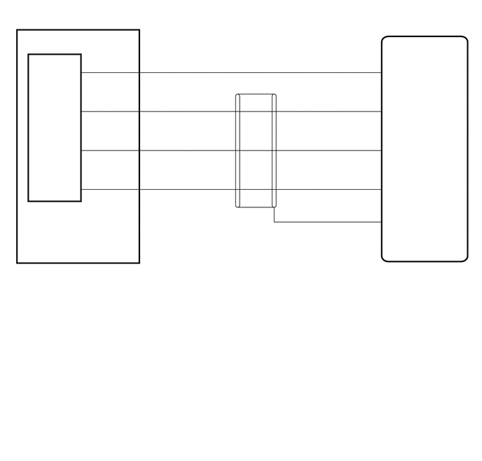
The radio and display receiver assembly, telephone microphone assembly are connected to each other using the microphone connection detection signal lines.
WIRING DIAGRAM
CAUTION / NOTICE / HINT
- NOTICE:
-
When replacing the radio and display receiver assembly, always replace it with a new one. If a radio and display receiver assembly which was installed to another vehicle is used, the following may occur:
- ·
A communication malfunction DTC may be stored.
·The radio and display receiver assembly may not operate normally.
- HINT:
-
Depending on the parts that are replaced during vehicle inspection or maintenance, performing initialization, registration or calibration may be needed. Refer to Precaution for Audio and Visual System.
PROCEDURE
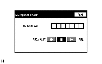
Enter the "Microphone Check" screen. Refer to Check Microphone in Operation Check.
When a voice is input into the microphone, check that the microphone input level meter changes according to the input voice.
- OK:
Check result is normal.
- Result:
Proceed to OK NG
OK
NG
Choose the model to be inspected.
- Result:
Result Proceed to except Wagon A for Wagon and w/ Telematics Transceiver B for Wagon and w/o Telematics Transceiver C
A
B
C
Disconnect the O7 radio and display receiver assembly connector.
Disconnect the a19 map light assembly connector.
Measure the resistance according to the value(s) in the table below.
- Standard Resistance:
Tester Connection Condition Specified Condition O7-25 (SNS2) - a19-11 (SNS2) Always Below 1 Ω O7-23 (MACC) - a19-8 (MACC) Always Below 1 Ω O7-21 (MIN+) - a19-9 (MCO+) Always Below 1 Ω O7-22 (MIN-) - a19-10 (MCO-) Always Below 1 Ω O7-25 (SNS2) - Body ground Always 10 kΩ or higher O7-23 (MACC) - Body ground Always 10 kΩ or higher O7-21 (MIN+) - Body ground Always 10 kΩ or higher O7-22 (MIN-) - Body ground Always 10 kΩ or higher O7-24 (SGND) - Body ground Always 10 kΩ or higher
- Result:
Proceed to OK NG
OK
NG
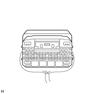
| *a | Component with harness connected
(Radio and Display Receiver Assembly) |
Remove the radio and display receiver assembly with the connector(s) still connected.
Measure the voltage according to the value(s) in the table below.
- Standard Voltage:
Tester Connection Switch Condition Specified Condition O7-23 (MACC) - Body ground Ignition switch ACC 4 to 6 V
Measure the resistance according to the value(s) in the table below.
- Standard Resistance:
Tester Connection Condition Specified Condition O7-24 (SGND) - Body ground Always Below 1 Ω O7-22 (MIN-) - Body ground Always Below 1 Ω
- Result:
Proceed to OK NG
OK
NG
| *a | Component with harness connected
(Map Light Assembly) |
Remove the map light assembly with the connector(s) still connected.
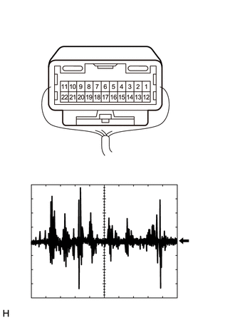
Connect an oscilloscope to terminal a19-9 (MCO+) and a19-10 (MCO-).
Check the signal waveform according to the condition(s) in the table below.
| Item | Condition |
|---|---|
| Measurement terminal | a19-9 (MCO+) - a19-10 (MCO-) |
| Tool setting | 50 mV/DIV., 500 ms/DIV. |
| Vehicle condition | 1.
Turn the ignition switch to ACC. 2.
Sound is input to the map light assembly when the user is closer than 125 mm from the map light assembly sound holes. |
- OK:
The waveform is similar to that shown in the illustration.
- HINT:
-
The oscilloscope waveform shown in the illustration is an example for reference only.
- Result:
Proceed to OK NG
OK
NG
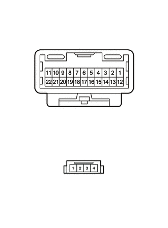
| *a | Component without harness connected
(Map Light Assembly [Wire Harness Side]) |
| *b | Component without harness connected
(Map Light Assembly [Telephone Microphone Assembly Side]) |
Remove the map light assembly.
Disconnect the telephone microphone assembly connector.
Measure the resistance according to the value(s) in the table below.
- Standard Resistance:
Tester Connection Condition Specified Condition a19-11 (SNS2) - A-1 (SNS2) Always Below 1 Ω a19-8 (MACC) - A-4 (MACC) Always Below 1 Ω a19-9 (MCO+) - A-3 (MIC+) Always Below 1 Ω a19-10 (MCO-) - A-2 (MIC-) Always Below 1 Ω a19-11 (SNS2) - a19-10 (MCO-) Always 10 kΩ or higher a19-11 (SNS2) - a19-9 (MCO+) Always 10 kΩ or higher a19-11 (SNS2) - a19-8 (MACC) Always 10 kΩ or higher a19-10 (MCO-) - a19-9 (MCO+) Always 10 kΩ or higher a19-10 (MCO-) - a19-8 (MACC) Always 10 kΩ or higher a19-9 (MCO+) - a19-8 (MACC) Always 10 kΩ or higher
- Result:
Proceed to OK NG
OK
NG
Disconnect the O7 radio and display receiver assembly connector.
Disconnect the a22 map light assembly connector.
Measure the resistance according to the value(s) in the table below.
- Standard Resistance:
Tester Connection Condition Specified Condition O7-25 (SNS2) - a22-3 (SNS2) Always Below 1 Ω O7-23 (MACC) - a22-6 (MACC) Always Below 1 Ω O7-21 (MIN+) - a22-5 (MCO+) Always Below 1 Ω O7-22 (MIN-) - a22-4 (MCO-) Always Below 1 Ω O7-25 (SNS2) - Body ground Always 10 kΩ or higher O7-23 (MACC) - Body ground Always 10 kΩ or higher O7-21 (MIN+) - Body ground Always 10 kΩ or higher O7-22 (MIN-) - Body ground Always 10 kΩ or higher O7-24 (SGND) - Body ground Always 10 kΩ or higher
- Result:
Proceed to OK NG
OK
NG
| *a | Component with harness connected
(Radio and Display Receiver Assembly) |
Remove the radio and display receiver assembly with the connector(s) still connected.
Measure the voltage according to the value(s) in the table below.
- Standard Voltage:
Tester Connection Switch Condition Specified Condition O7-23 (MACC) - Body ground Ignition switch ACC 4 to 6 V
Measure the resistance according to the value(s) in the table below.
- Standard Resistance:
Tester Connection Condition Specified Condition O7-24 (SGND) - Body ground Always Below 1 Ω O7-22 (MIN-) - Body ground Always Below 1 Ω
- Result:
Proceed to OK NG
OK
NG
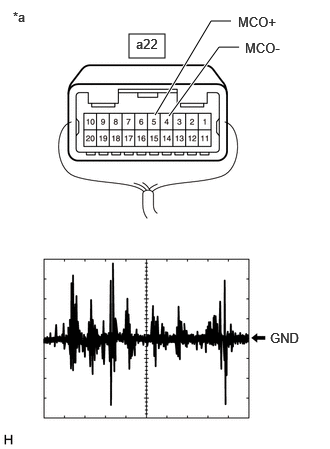
| *a | Component with harness connected
(Map Light Assembly) |
Remove the map light assembly with the connector(s) still connected.
Connect an oscilloscope to terminal a22-5 (MCO+) and a22-4 (MCO-).
Check the signal waveform according to the condition(s) in the table below.
| Item | Condition |
|---|---|
| Measurement terminal | a22-5 (MCO+) - a22-4 (MCO-) |
| Tool setting | 50 mV/DIV., 500 ms/DIV. |
| Vehicle condition | 1.
Turn the ignition switch to ACC. 2.
Sound is input to the map light assembly when the user is closer than 125 mm from the map light assembly sound holes. |
- OK:
The waveform is similar to that shown in the illustration.
- HINT:
-
The oscilloscope waveform shown in the illustration is an example for reference only.
- Result:
Proceed to OK NG
OK
NG
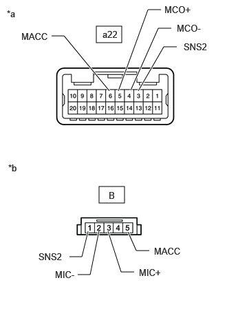
| *a | Component without harness connected
(Map Light Assembly [Wire Harness Side]) |
| *b | Component without harness connected
(Map Light Assembly [Telephone Microphone Assembly Side]) |
Remove the map light assembly.
Disconnect the telephone microphone assembly connector.
Measure the resistance according to the value(s) in the table below.
- Standard Resistance:
Tester Connection Condition Specified Condition a22-3 (SNS2) - B-1 (SNS2) Always Below 1 Ω a22-6 (MACC) - B-5 (MACC) Always Below 1 Ω a22-5 (MCO+) - B-3 (MIC+) Always Below 1 Ω a22-4 (MCO-) - B-2 (MIC-) Always Below 1 Ω a22-3 (SNS2) - a22-4 (MCO-) Always 10 kΩ or higher a22-3 (SNS2) - a22-5 (MCO+) Always 10 kΩ or higher a22-3 (SNS2) - a22-6 (MACC) Always 10 kΩ or higher a22-4 (MCO-) - a22-5 (MCO+) Always 10 kΩ or higher a22-4 (MCO-) - a22-6 (MACC) Always 10 kΩ or higher a22-5 (MCO+) - a22-6 (MACC) Always 10 kΩ or higher
- Result:
Proceed to OK NG
OK
NG
Disconnect the O7 radio and display receiver assembly connector.
Disconnect the a23 map light assembly connector.
Measure the resistance according to the value(s) in the table below.
- Standard Resistance:
Tester Connection Condition Specified Condition O7-25 (SNS2) - a23-12 (SNS2) Always Below 1 Ω O7-23 (MACC) - a23-9 (MACC) Always Below 1 Ω O7-21 (MIN+) - a23-10 (MCO+) Always Below 1 Ω O7-22 (MIN-) - a23-11 (MCO-) Always Below 1 Ω O7-25 (SNS2) - Body ground Always 10 kΩ or higher O7-23 (MACC) - Body ground Always 10 kΩ or higher O7-21 (MIN+) - Body ground Always 10 kΩ or higher O7-22 (MIN-) - Body ground Always 10 kΩ or higher O7-24 (SGND) - Body ground Always 10 kΩ or higher
- Result:
Proceed to OK NG
OK
NG
| *a | Component with harness connected
(Radio and Display Receiver Assembly) |
Remove the radio and display receiver assembly with the connector(s) still connected.
Measure the voltage according to the value(s) in the table below.
- Standard Voltage:
Tester Connection Switch Condition Specified Condition O7-23 (MACC) - Body ground Ignition switch ACC 4 to 6 V
Measure the resistance according to the value(s) in the table below.
- Standard Resistance:
Tester Connection Condition Specified Condition O7-24 (SGND) - Body ground Always Below 1 Ω O7-22 (MIN-) - Body ground Always Below 1 Ω
- Result:
Proceed to OK NG
OK
NG
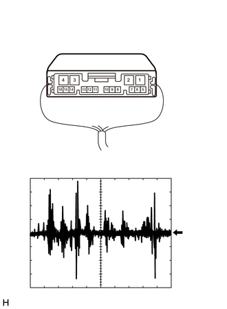
| *a | Component with harness connected
(Map Light Assembly) |
Remove the map light assembly with the connector(s) still connected.
Connect an oscilloscope to terminal a23-10 (MCO+) and a23-11 (MCO-).
Check the signal waveform according to the condition(s) in the table below.
| Item | Condition |
|---|---|
| Measurement terminal | a23-10 (MCO+) - a23-11 (MCO-) |
| Tool setting | 50 mV/DIV., 500 ms/DIV. |
| Vehicle condition | 1.
Turn the ignition switch to ACC. 2.
Sound is input to the map light assembly when the user is closer than 125 mm from the map light assembly sound holes. |
- OK:
The waveform is similar to that shown in the illustration.
- HINT:
-
The oscilloscope waveform shown in the illustration is an example for reference only.
- Result:
Proceed to OK NG
OK
NG
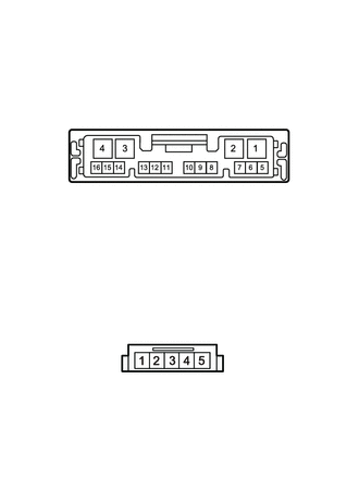
| *a | Component without harness connected
(Map Light Assembly [Wire Harness Side]) |
| *b | Component without harness connected
(Map Light Assembly [Telephone Microphone Assembly Side]) |
Remove the map light assembly.
Disconnect the telephone microphone assembly connector.
Measure the resistance according to the value(s) in the table below.
- Standard Resistance:
Tester Connection Condition Specified Condition a23-12 (SNS2) - B-1 (SNS2) Always Below 1 Ω a23-9 (MACC) - B-5 (MACC) Always Below 1 Ω a23-10 (MCO+) - B-3 (MIC+) Always Below 1 Ω a23-11 (MCO-) - B-2 (MIC-) Always Below 1 Ω a23-12 (SNS2) - a23-11 (MCO-) Always 10 kΩ or higher a23-12 (SNS2) - a23-10 (MCO+) Always 10 kΩ or higher a23-12 (SNS2) - a23-9 (MACC) Always 10 kΩ or higher a23-11 (MCO-) - a23-10 (MCO+) Always 10 kΩ or higher a23-11 (MCO-) - a23-9 (MACC) Always 10 kΩ or higher a23-10 (MCO+) - a23-9 (MACC) Always 10 kΩ or higher
- Result:
Proceed to OK NG
OK
NG