LIGHTING (EXT) LIGHTING SYSTEM(w/ Headlight ECU) TERMINALS OF ECU
CHECK MAIN BODY ECU (MULTIPLEX NETWORK BODY ECU) AND INSTRUMENT PANEL JUNCTION BLOCK ASSEMBLY
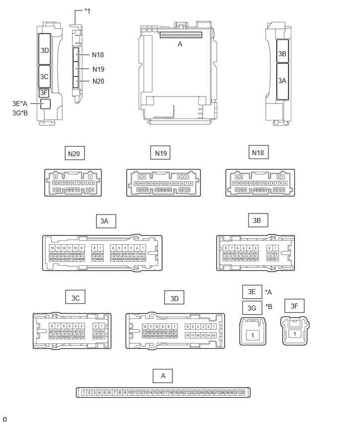
| *A | for LHD | *B | for RHD |
| *1 | Main Body ECU (Multiplex Network Body ECU) | - | - |
Remove the main body ECU (multiplex network body ECU) from the instrument panel junction block assembly.
Connect the instrument panel junction block assembly connectors.
Measure the voltage and resistance according to the value(s) in the table below.
| Terminal No. (Symbol) | Wiring Color | Terminal Description | Condition | Specified Condition |
|---|---|---|---|---|
| A-32 (IG) - Body ground | None - Body ground | Ignition power supply | Engine switch on (IG) | 10.5 to 16 V*1
11 to 14 V*2 |
| Engine switch off | Below 1 V | |||
| A-31 (BECU) - Body ground | None - Body ground | Battery power supply | Engine switch off | 11 to 14 V |
| A-30 (ACC) - Body ground | None - Body ground | ACC power supply | Engine switch on (ACC) | 11 to 14 V |
| Engine switch off | Below 1 V | |||
| A-11 (GND1) - Body ground | None - Body ground | Ground | Always | Below 1 Ω |
*1: w/ Stop and Start System
*2: w/o Stop and Start System
Install the main body ECU (multiplex network body ECU).
Measure the voltage and resistance, and check for pulses according to the value(s) in the table below.
| Terminal No. (Symbol) | Wiring Color | Terminal Description | Condition | Specified Condition |
|---|---|---|---|---|
| 3C-25 (FFGO) - Body ground | V - Body ground | Fog light switch input | Taillights on, fog light switch in Fr position | 11 to 14 V |
| Taillights on, fog light switch OFF | Below 1 V | |||
| 3C-19 - Body ground | L - Body ground | BKUP LP relay drive output | Engine switch off, shift lever not in R | Below 1 V |
| Engine switch on (IG), shift lever in R | 11 to 14 V | |||
| 3C-31 (HRLY) - Body ground | L - Body ground | H-LP LH relay drive output | Light control switch in HEAD position | Below 1 V |
| Light control switch not in HEAD position | 11 to 14 V | |||
| 3C-32 (TRLY) - Body ground | G - Body ground | Front fog lights drive output | Light control switch in TAIL or HEAD position | 11 to 14 V |
| Light control switch in neither TAIL nor HEAD position | Below 1 V | |||
| 3B-11 (TRLY) - Body ground | LG - Body ground | Taillights and license plate lights drive output | Light control switch in TAIL or HEAD position | 11 to 14 V |
| Light control switch in neither TAIL nor HEAD position | Below 1 V | |||
| N18-19 (GND2) - Body ground | W-B - Body ground | Ground | Always | Below 1 Ω |
| N20-21 (AHID) - Body ground*1 | L - Body ground | Auto high beam switch indicator drive output | Engine switch on (IG), auto high beam switch on | Below 1 V |
| Engine switch on (IG), auto high beam switch off | 11 to 14 V | |||
| N19-12 (HRY2) - Body ground | L - Body ground | H-LP RH relay drive output | Light control switch in HEAD position | Below 1 V |
| Light control switch not in HEAD position | 11 to 14 V | |||
| N19-16 (HEAD) - Body ground | B - Body ground | Light control switch HEAD position input | Light control switch in HEAD position | Below 1 V |
| Light control switch not in HEAD position | 11 to 14 V | |||
| N19-23 (CLTB) - N19-25 (CLTE) | L - G | Automatic light control sensor power supply output | Engine switch on (IG) | 11 to 14 V |
| N19-24 (CLTS) - Body ground | R - Body ground | Automatic light control sensor signal input | Engine switch off | Below 1 V |
| Engine switch on (IG) | Pulse generation
(See waveform 1) |
|||
| N19-26 (AHBI) - Body ground*1 | V - Body ground | Auto high beam switch signal input | Auto high beam switch on | Below 1 V |
| Auto high beam switch off | 11 to 14 V | |||
| 3A-38 (PKB) - Body ground | B - Body ground | Parking brake switch signal input | Parking brake switch on | Below 1 V |
| Parking brake switch off | 11 to 14 V | |||
| 3D-21 (RFGO) - Body ground*2 | G - Body ground | Rear fog light drive output | Taillights on, fog light switch in Fr&Rr position | 11 to 14 V |
| Taillights on, fog light switch in off position | Below 1 V |
*1: w/ Automatic High Beam System
*2: w/ Rear Fog Light
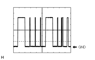
Waveform 1
| Item | Content |
|---|---|
| Tester Connection | N19-24 (CLTS) - Body ground |
| Tool setting | 2 V/DIV., 10 ms./DIV. |
| Condition | Engine switch on (IG) |
- HINT:
-
The communication waveform changes according to the surrounding brightness.
CHECK HEADLIGHT ECU SUB-ASSEMBLY LH
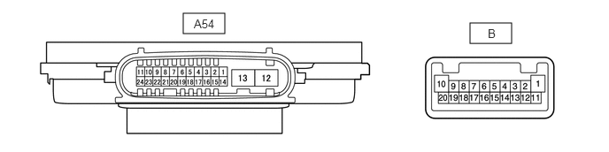
Disconnect the A54 headlight ECU sub-assembly LH connector.
Measure the voltage and resistance according to the value(s) in the table below.
| Terminal No. (Symbol) | Wiring Color | Terminal Description | Condition | Specified Condition |
|---|---|---|---|---|
| A54-4 (IG) - Body ground | R - Body ground | Ignition power supply | Engine switch off | Below 1 V |
| Engine switch on (IG) | 11 to 14 V | |||
| A54-12 (GND) - Body ground | W-B - Body ground | Ground | Always | Below 1 Ω |
| A54-13 (ECUB) - Body ground | P - Body ground | Battery power supply | ·
15 seconds or more after engine switch turned off ·
Taillights off |
Below 1 V |
·
Engine switch on (IG) or within 15 seconds after engine switch turned off ·
Taillights on |
11 to 14 V |
Connect the A54 headlight ECU sub-assembly LH connector.
- HINT:
- ·
Since the A54 headlight ECU sub-assembly LH connector is a waterproof type connector, the voltage and pulses cannot be checked directly. The values listed are for reference only.
·Since the B headlight ECU sub-assembly LH connectors are connected inside the headlight assembly, the voltage and pulses cannot be checked directly. The values listed are for reference only.
Measure the voltage and check of pulses according to the value(s) in the table below.
| Terminal No. (Symbol) | Wiring Color | Terminal Description | Condition | Specified Condition |
|---|---|---|---|---|
|
*1: w/ Daytime Running Light *2: w/o Daytime Running Light |
||||
| A54-11 (TNS) - Body ground | L - Body ground | Front turn signal light LH signal input | Engine switch on (IG), front turn signal light LH off | Below 1 V |
| Engine switch on (IG), front turn signal light LH blinking | 11 to 14 V ←→ Below 1 V | |||
| A54-16 (SBR) - A54-15 (SGR) | LG - SB | Rear height control sensor sub-assembly LH power supply | Engine switch on (IG) | 4.75 to 5.25 V |
| A54-17 (SHRL) - A54-15 (SGR) | GR - SB | Rear height control sensor sub-assembly LH signal input | Engine switch on (IG), vehicle unloaded, vehicle stopped | Approximately 2.5 V
(value decreases as the front of the vehicle is raised) |
| A54-23 (CANL) - Body ground | W - Body ground | CAN communication line | Engine switch off | Below 1 V |
| Engine switch on (IG) | Pulse generation | |||
| A54-24 (CANH) - Body ground | P - Body ground | CAN communication line | Engine switch off | Below 1 V |
| Engine switch on (IG) | Pulse generation | |||
| B-2 (LOLED2) - B-3 (LOLED1) | - | Low beam headlight LH drive output | Low beam headlight LH off | Below 1 V |
| Low beam headlight LH on | 12.9 to 14.1 V | |||
| B-9 (ACTBI) - B-17 (ACTGI) | - | Headlight leveling motor power source | Engine switch off | Below 1 V |
| Engine switch on (IG) | 11 to 14 V | |||
| B-8 (ACTSI) - B-17 (ACTGI) | - | Headlight leveling motor LH signal output | Engine switch on (IG), low beam headlight LH on, vehicle height not changed | Below 1 V |
| Engine switch on (IG), low beam headlight LH on, vehicle height changed and maintained for more than 3 seconds | 1 to 14 V | |||
| B-20 (TURN+) - B-13 (TURN-) | - | Front turn signal light LH signal output | Engine switch on (IG), front turn signal light LH off | Below 1 V |
| Engine switch on (IG), front turn signal light LH blinking | 11 to 14 V ←→ Below 1 V | |||
| B-10 (DRL/CLL+) - B-1 (DRL/CLL-)*1 | - | Left clearance lights/daytime running lights power source | Left clearance lights and daytime running lights off | Below 1 V |
| Left clearance lights and daytime running lights on | 11 to 14 V | |||
| B-16 (PWM1) - B-1 (DRL/CLL-)*1 | - | Left clearance lights/daytime running lights control signal output | Left clearance lights and daytime running lights off | Below 1 V |
| Left clearance lights on | Pulse generation | |||
| Left daytime running lights on | 0.4 to 0.5 V | |||
| B-18 (CLL+) - B-12 (CLL-)*2 | - | Left clearance lights signal output | Left clearance lights off | Below 1 V |
| Left clearance lights on | 11 to 14 V | |||
| B-19 (HI SOL+) - B-11 (HI SOL-) | - | High beam headlight LH drive output | High beam headlight LH off | Below 1 V |
| High beam headlight LH on | 11 to 14 V | |||
CHECK HEADLIGHT ECU SUB-ASSEMBLY RH
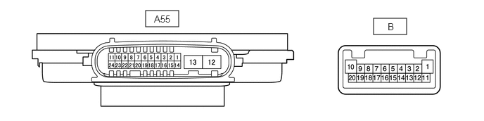
Disconnect the A55 headlight ECU sub-assembly RH connector.
Measure the voltage and resistance according to the value(s) in the table below.
| Terminal No. (Symbol) | Wiring Color | Terminal Description | Condition | Specified Condition |
|---|---|---|---|---|
| A55-4 (IG) - Body ground | P - Body ground | Ignition power supply | Engine switch off | Below 1 V |
| Engine switch on (IG) | 11 to 14 V | |||
| A55-12 (GND) - Body ground | W-B - Body ground | Ground | Always | Below 1 Ω |
| A55-13 (ECUB) - Body ground | B - Body ground | Battery power supply | ·
15 seconds or more after engine switch turned off ·
Taillights off |
Below 1 V |
·
Engine switch on (IG) or within 15 seconds after engine switch turned off ·
Taillights on |
11 to 14 V |
Connect the A55 headlight ECU sub-assembly RH connector.
- HINT:
- ·
Since the A55 headlight ECU sub-assembly RH connector is a waterproof type connector, the voltage and pulses cannot be checked directly. The values listed are for reference only.
·Since the B headlight ECU sub-assembly RH connectors are connected inside the headlight assembly, the voltage and pulses cannot be checked directly. The values listed are for reference only.
Measure the voltage and check of pulses according to the value(s) in the table below.
| Terminal No. (Symbol) | Wiring Color | Terminal Description | Condition | Specified Condition |
|---|---|---|---|---|
|
*1: w/ Daytime Running Light *2: w/o Daytime Running Light |
||||
| A55-11 (TNS) - Body ground | R - Body ground | Front turn signal light RH signal input | Engine switch on (IG), front turn signal light RH off | Below 1 V |
| Engine switch on (IG), front turn signal light RH blinking | 11 to 14 V ←→ Below 1 V | |||
| A55-23 (CANL) - Body ground | W - Body ground | CAN communication line | Engine switch off | Below 1 V |
| Engine switch on (IG) | Pulse generation | |||
| A55-24 (CANH) - Body ground | G - Body ground | CAN communication line | Engine switch off | Below 1 V |
| Engine switch on (IG) | Pulse generation | |||
| B-2 (LOLED2) - B-3 (LOLED1) | - | Low beam headlight RH drive output | Low beam headlight RH off | Below 1 V |
| Low beam headlight RH on | 12.9 to 14.1 V | |||
| B-9 (ACTBI) - B-17 (ACTGI) | - | Headlight leveling motor power source | Engine switch off | Below 1 V |
| Engine switch on (IG) | 11 to 14 V | |||
| B-8 (ACTSI) - B-17 (ACTGI) | - | Headlight leveling motor RH signal output | Engine switch on (IG), low beam headlight RH on, vehicle height not changed | Below 1 V |
| Engine switch on (IG), low beam headlight RH on, vehicle height changed and maintained for more than 3 seconds | 1 to 14 V | |||
| B-20 (TURN+) - B-13 (TURN-) | - | Front turn signal RH light signal output | Engine switch on (IG), front turn signal light RH off | Below 1 V |
| Engine switch on (IG), front turn signal light RH blinking | 11 to 14 V ←→ Below 1 V | |||
| B-10 (DRL/CLL+) - B-1 (DRL/CLL-)*1 | - | Right clearance lights/daytime running lights power source | Right clearance lights and daytime running lights off | Below 1 V |
| Right clearance lights and daytime running lights on | 11 to 14 V | |||
| B-16 (PWM1) - B-1 (DRL/CLL-)*1 | - | Right clearance lights/daytime running lights control signal output | Right clearance lights and daytime running lights off | Below 1 V |
| Right clearance lights on | Pulse generation | |||
| Right daytime running lights on | 0.4 to 0.5 V | |||
| B-18 (CLL+) - B-12 (CLL-)*2 | - | Right clearance lights/daytime running lights control signal output | Right clearance lights off | Below 1 V |
| Right clearance lights on | 11 to 14 V | |||
| B-19 (HI SOL+) - B-11 (HI SOL-) | - | High beam headlight RH drive output | High beam headlight RH off | Below 1 V |
| High beam headlight RH on | 11 to 14 V | |||
CHECK COMBINATION METER ASSEMBLY
CHECK FORWARD RECOGNITION CAMERA (w/ Automatic High Beam System)