DOOR LOCK WIRELESS DOOR LOCK CONTROL SYSTEM(w/o Entry and Start System) No Answer-Back
DESCRIPTION
In some cases, wireless door lock control functions are normal but the hazard warning light and/or wireless door lock buzzer answer-back function* does not operate. In such cases, hazard warning light and wireless door lock buzzer* signal output from the main body ECU (multiplex network body ECU) may be malfunctioning.
*: w/ Wireless Door Lock Buzzer Answer-back Function
WIRING DIAGRAM
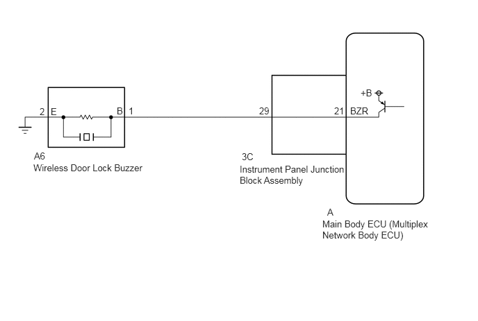
CAUTION / NOTICE / HINT
- NOTICE:
-
The wireless door lock control system uses the CAN communication system. Inspect the communication function by following How to Proceed with Troubleshooting. Troubleshoot the wireless door lock control system after confirming that the communication system is functioning properly.
PROCEDURE
Connect the GTS to the DLC3.
Turn the ignition switch to ON.
Turn the GTS on.
Enter the following menus: Customize Setting / Wireless Door Lock.
Select the setting by referring to the table below.
- Wireless Door Lock
-
Tester Display Description Default Setting ECU Hazard Answer Back Function that flashes the hazard warning lights once when the doors are locked by wireless operation and twice when the doors are unlocked by wireless operation ON 0:OFF,1:ON Main body ECU (Multiplex network body ECU) Wireless Buzzer Resp Wireless door lock buzzer response* ON 0:OFF,1:ON Main body ECU (Multiplex network body ECU) Wireless Buzzer Volume Wireless door lock buzzer volume* Level5 0000:Level7,0001:Level6,0010:Level5,0011:Level4,0100:Level3,0101:Level2,0110:Level1,0111:Level0 Main body ECU (Multiplex network body ECU) - 50006 1
*: w/ Wireless Door Lock Buzzer Answer-back Function
- Result:
Proceed to Both items are ON and except Level 0 Either item is OFF or Level 0
Both items are ON and except Level 0
Either item is OFF or Level 0
Check the wireless door lock control function using the door control transmitter module set sub-assembly.
- Result:
Proceed to Wireless door lock/unlock operates properly Wireless door lock/unlock does not operate properly
Wireless door lock/unlock operates properly
Wireless door lock/unlock does not operate properly
Connect the GTS to the DLC3.
Turn the ignition switch to ON.
Turn the GTS on.
Enter the following menus: Body Electrical / Main Body / Data List.
Read the Data List according to the display on the GTS.
- Body Electrical > Main Body > Data List
-
Tester Display Measurement Item Range Normal Condition Diagnostic Note FR Door Lock Pos Front door RH unlock detection switch signal LOCK or UNLOCK LOCK: Front door RH locked
UNLOCK: Front door RH unlocked- FL Door Lock Pos Front door LH unlock detection switch signal LOCK or UNLOCK LOCK: Front door LH locked
UNLOCK: Front door LH unlocked- RR-Door Lock Pos SW Slide door RH unlock detection switch signal*1 OFF or ON OFF: Slide door RH locked
ON: Slide door RH unlocked- RL-Door Lock Pos SW Slide door LH unlock detection switch signal*2 OFF or ON OFF: Slide door LH locked
ON: Slide door LH unlocked-
*1: w/ Slide Door RH
*2: w/ Slide Door LH
- Body Electrical > Main Body > Data List
-
Tester Display FR Door Lock Pos FL Door Lock Pos RR-Door Lock Pos SW RL-Door Lock Pos SW - 50003 123 196,198,51,52
- OK:
The GTS display changes correctly in response to the lock/unlock operation.
- Result:
Proceed to OK NG
OK
NG
Check the wireless answer-back operation using the door control transmitter module set sub-assembly.
- Result:
Result Proceed to Only wireless door lock buzzer answer-back does not occur.* A Only hazard warning light answer-back does not occur. B
*: w/ Wireless Door Lock Buzzer Answer-back Function
A
B
Connect the GTS to the DLC3.
Turn the ignition switch to ON.
Turn the GTS on.
Enter the following menus: Body Electrical / Main Body / Active Test.
Perform Active Test according to the display on the GTS.
- Body Electrical > Main Body > Active Test
-
Tester Display Measurement Item Control Range Diagnostic Note Wireless Buzzer Wireless door lock buzzer OFF/ON -
- Body Electrical > Main Body > Active Test
-
Tester Display Wireless Buzzer - 50004 123 12
- Result:
Result Proceed to Wireless buzzer does not sound A Wireless buzzer sounds B
A
B
Disconnect the A6 wireless door lock buzzer connector.
Perform the Active Test using the GTS and sound the wireless door lock buzzer.
- Body Electrical > Main Body > Active Test
-
Tester Display Measurement Item Control Range Diagnostic Note Wireless Buzzer Wireless door lock buzzer OFF/ON -
- Body Electrical > Main Body > Active Test
-
Tester Display Wireless Buzzer - 50004 123 12
While performing the Active Test, measure the voltage between the terminals of the wireless door lock buzzer.
- Standard Voltage:
Tester Connection Condition Specified Condition A6-1 (B) - A6-2 (E) Active Test Wireless Buzzer ON Pulse generation
(frequency: 2 kHz, high voltage: 11 to 14 V, low voltage: below 1 V)Active Test Wireless Buzzer OFF Below 1 V
- Result:
Proceed to OK NG
OK
for LHD:
for RHD:
NG
Remove the main body ECU (multiplex network body ECU) from the instrument panel junction block assembly.
Disconnect the A6 wireless door lock buzzer connector.
Reconnect the 3C instrument panel junction block assembly connector.
Measure the resistance according to the value(s) in the table below.
- Standard Resistance:
Tester Connection Condition Specified Condition A6-1 (B) - A-21 (BZR) Always Below 1 Ω A6-2 (E) - Body ground Always Below 1 Ω A6-1 (B) or A-21 (BZR) - Other terminals and body ground Always 10 kΩ or higher
- Result:
Result Proceed to OK A NG (E terminal) B NG (Other terminal) C
A
B
C
Check that the hazard warning lights blink when the hazard warning signal switch is pressed.
- OK:
Hazard warning lights blink.
- Result:
Proceed to OK NG
OK
NG
Disconnect the 3C instrument panel junction block assembly connector.
Disconnect the A6 wireless door lock buzzer connector.
Measure the resistance according to the value(s) in the table below.
- Standard Resistance:
Tester Connection Condition Specified Condition A6-1 (B) - 3C-29 Always Below 1 Ω A6-1 (B) or 3C-29 - Other terminals and body ground Always 10 kΩ or higher
- Result:
Proceed to OK NG
OK
NG