LIGHTING (EXT) LIGHTING SYSTEM(w/o Headlight ECU) TERMINALS OF ECU
CHECK MAIN BODY ECU (MULTIPLEX NETWORK BODY ECU) AND INSTRUMENT PANEL JUNCTION BLOCK ASSEMBLY
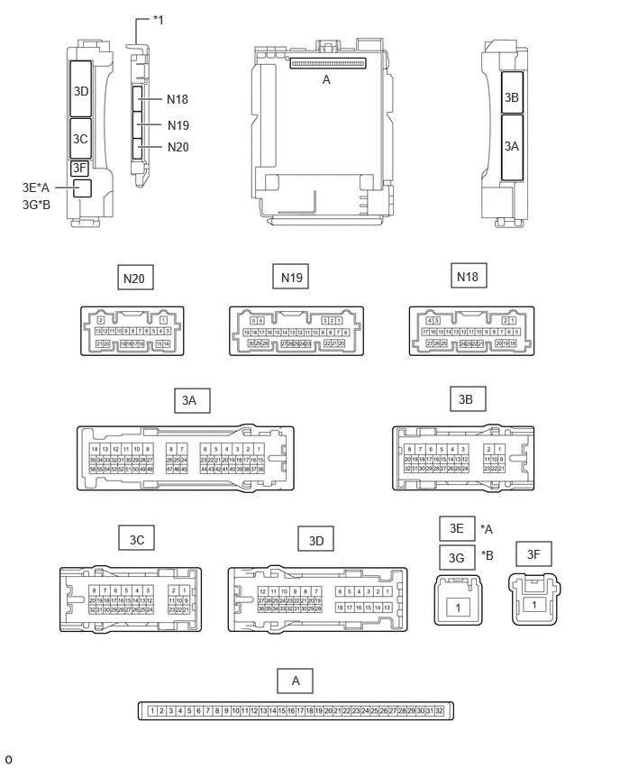
| *A | for LHD | *B | for RHD |
| *1 | Main Body ECU (Multiplex Network Body ECU) | - | - |
Remove the main body ECU (multiplex network body ECU) from the instrument panel junction block assembly.
for LHD:
for RHD:
Connect the instrument panel junction block assembly connectors.
Measure the voltage and resistance according to the value(s) in the table below.
| Terminal No. (Symbol) | Wiring Color | Terminal Description | Condition | Specified Condition |
|---|---|---|---|---|
| A-32 (IG) - Body ground | None - Body ground | Ignition power supply | Ignition switch ON | 11 to 14 V |
| Ignition switch off | Below 1 V | |||
| A-31 (BECU) - Body ground | None - Body ground | Battery power supply | Always | 11 to 14 V |
| A-30 (ACC) - Body ground | None - Body ground | ACC power supply | Ignition switch ACC | 11 to 14 V |
| Ignition switch off | Below 1 V | |||
| A-11 (GND1) - Body ground | None - Body ground | Ground | Always | Below 1 Ω |
Install the main body ECU (multiplex network body ECU).
for LHD:
for RHD:
Measure the voltage and resistance, and check for pulses according to the value(s) in the table below.
| Terminal No. (Symbol) | Wiring Color | Terminal Description | Condition | Specified Condition |
|---|---|---|---|---|
| 3C-25 (FFGO) - Body ground*1 | V - Body ground | Fog light switch input | Taillights on, fog light switch in Fr position | 11 to 14 V |
| Taillights on, fog light switch OFF | Below 1 V | |||
| 3C-19 - Body ground*2 | L - Body ground | BKUP LP relay drive output | Ignition switch off, shift lever not in R | Below 1 V |
| Ignition switch ON, shift lever in R | 11 to 14 V | |||
| 3C-28 (DRL) - Body ground | W - Body ground | Daytime running light system drive output | Daytime running light system operating | Below 1 V |
| Daytime running light system not operating | 11 to 14 V | |||
| 3C-31 (HRLY) - Body ground | L - Body ground | H-LP LH relay drive output | Light control switch in HEAD position | Below 1 V |
| Light control switch not in HEAD position | 11 to 14 V | |||
| 3C-32 (TRLY) - Body ground | G - Body ground | Front fog lights*1 and clearance lights drive output | Light control switch in TAIL or HEAD position | 11 to 14 V |
| Light control switch in neither TAIL nor HEAD position | Below 1 V | |||
| 3B-11 (TRLY) - Body ground | LG - Body ground | Taillights and license plate lights drive output | Light control switch in TAIL or HEAD position | 11 to 14 V |
| Light control switch in neither TAIL nor HEAD position | Below 1 V | |||
| N18-19 (GND2) - Body ground | W-B - Body ground | Ground | Always | Below 1 Ω |
| N20-21 (AHID) - Body ground*4 | L - Body ground | Auto high beam switch indicator drive output | Ignition switch ON, auto high beam switch on | Below 1 V |
| Ignition switch ON, auto high beam switch off | 11 to 14 V | |||
| N19-12 (HRY2) - Body ground | BE - Body ground | H-LP RH relay drive output | Light control switch in HEAD position | Below 1 V |
| Light control switch not in HEAD position | 11 to 14 V | |||
| N19-13 (DIM) - Body ground | GR - Body ground | High beam headlight drive output | Light control switch in HEAD position and headlight dimmer switch in High or Flash position | Below 1 V |
| Headlight dimmer switch not in High or Flash position | 11 to 14 V | |||
| N19-16 (HEAD) - Body ground | B - Body ground | Light control switch HEAD position input | Light control switch in HEAD position | Below 1 V |
| Light control switch not in HEAD position | 11 to 14 V | |||
| N19-23 (CLTB) - N19-25 (CLTE)*3 | L - G | Automatic light control sensor power supply output | Ignition switch ON | 11 to 14 V |
| N19-24 (CLTS) - Body ground*3 | R - Body ground | Automatic light control sensor signal input | Ignition switch off | Below 1 V |
| Ignition switch ON | Pulse generation
(See waveform 1) |
|||
| N19-25 (CLTE) - Body ground*3 | G - Body ground | Automatic light control sensor ground | Ignition switch ON | Below 1 Ω |
| N19-26 (AHBI) - Body ground*4 | V - Body ground | Auto high beam switch signal input | Auto high beam switch on | Below 1 V |
| Auto high beam switch off | 11 to 14 V | |||
| 3A-38 (PKB) - Body ground | B - Body ground | Parking brake switch signal input | Parking brake switch on | Below 1 V |
| Parking brake switch off | 11 to 14 V |
*1: w/ Front Fog Light
*2: for Automatic Transmission
*3: w/ Automatic Light Control System
*4: w/ Automatic High Beam System
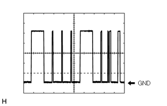
Waveform 1
| Item | Content |
|---|---|
| Tester Connection | N19-24 (CLTS) - Body ground |
| Tool setting | 2 V/DIV., 10 ms./DIV. |
| Condition | Ignition switch ON |
- HINT:
-
The communication waveform changes according to the surrounding brightness.
CHECK COMBINATION METER ASSEMBLY
CHECK FORWARD RECOGNITION CAMERA