DOOR LOCK KEY REMINDER WARNING SYSTEM Key Reminder Buzzer does not Sound
DESCRIPTION
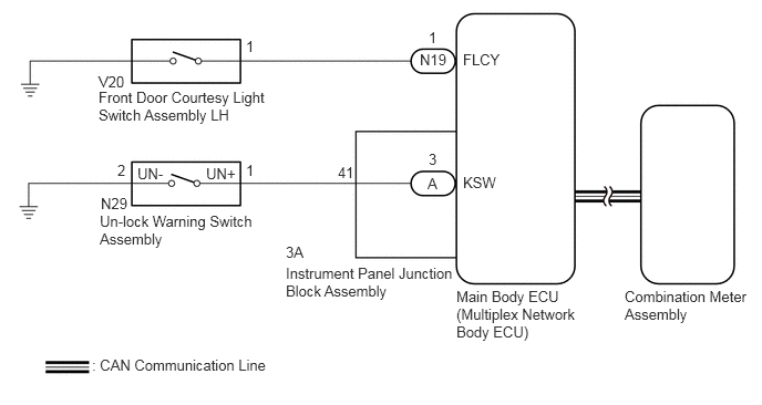
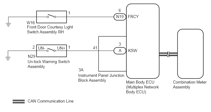
The key reminder warning buzzer sounds when the driver door is opened while the ignition switch is off or ACC. The key reminder warning buzzer is activated when the main body ECU (multiplex network body ECU) sends an unlock warning switch signal and driver door courtesy light switch signal to the combination meter assembly via CAN communication.
WIRING DIAGRAM
for LHD:
for RHD:
CAUTION / NOTICE / HINT
- NOTICE:
- ·
The key reminder warning system uses the CAN communication system. Inspect the communication function by following How to Proceed with Troubleshooting. Troubleshoot the key reminder warning system after confirming that the communication systems are functioning properly.
·When replacing the combination meter assembly, always replace it with a new one. If a combination meter assembly which was installed to another vehicle is used, the information stored in it will not match the information from the vehicle and a DTC may be stored.
PROCEDURE
Connect the GTS to the DLC3.
Turn the ignition switch to ON.
Turn the GTS on.
Enter the following menus: Body Electrical / Combination Meter / Active Test.
Perform the Active Test according to the display on the GTS.
- Body Electrical > Combination Meter > Active Test
-
Tester Display Measurement Item Control Range Diagnostic Note Buzzer Operation (800Hz, Vol L, W/ Damping) Combination meter buzzer
·Frequency: 800Hz
·Volume: Large
·Fading tone
ON -
- Body Electrical > Combination Meter > Active Test
-
Tester Display Buzzer Operation (800Hz, Vol L, W/ Damping) - 50004 409 13
- Result:
Result Proceed to Combination meter buzzer sounds A Combination meter buzzer does not sound B
A
B
Connect the GTS to the DLC3.
Turn the ignition switch to ON.
Turn the GTS on.
Enter the following menus: Body Electrical / Main Body / Data List.
Read the Data List according to the display on the GTS.
- Body Electrical > Main Body > Data List
-
Tester Display Measurement Item Range Normal Condition Diagnostic Note FR Door Courtesy SW Front door courtesy light switch RH signal*1 ON or OFF ON: Front door RH open
OFF: Front door RH closed- FL Door Courtesy SW Front door courtesy light switch LH signal*2 ON or OFF ON: Front door LH open
OFF: Front door LH closed-
*1: for RHD
*2: for LHD
- Body Electrical > Main Body > Data List
-
Tester Display FR Door Courtesy SW FL Door Courtesy SW - 50003 123 197,199
- OK:
The GTS indicates ON or OFF according to the driver door condition shown in the table.
- Result:
Proceed to OK NG
OK
NG
Connect the GTS to the DLC3.
Turn the ignition switch to ON.
Turn the GTS on.
Enter the following menus: Body Electrical / Main Body / Data List.
Read the Data List according to the display on the GTS.
- Body Electrical > Main Body > Data List
-
Tester Display Measurement Item Range Normal Condition Diagnostic Note Key Unlock Warning SW Un-lock warning switch signal ON or OFF ON: Key in ignition key cylinder
OFF: No key in ignition key cylinder-
- Body Electrical > Main Body > Data List
-
Tester Display Key Unlock Warning SW - 50003 123 32
- OK:
The GTS indicates ON or OFF according to whether the key is in the ignition key cylinder.
- Result:
Proceed to OK NG
OK
NG
Remove the un-lock warning switch assembly.
Inspect the un-lock warning switch assembly.
- Result:
Proceed to OK NG
OK
NG
Disconnect the N29 un-lock warning switch assembly connector.
Disconnect the 3A instrument panel junction block assembly connector.
Measure the resistance according to the value(s) in the table below.
- Standard Resistance:
Tester Connection Condition Specified Condition 3A-41 - N29-1 (UN+) Always Below 1 Ω N29-2 (UN-) - Body ground Always Below 1 Ω N29-1 (UN+) or 3A-41 - Other terminals and body ground Always 10 kΩ or higher
- Result:
Proceed to OK NG
OK
NG
Remove the instrument panel junction block assembly.
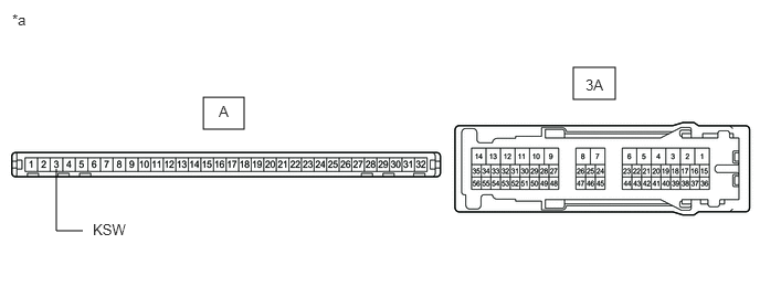
| *a | Component without harness connected
(Instrument Panel Junction Block Assembly) |
- | - |
Remove the main body ECU (multiplex network body ECU) from the instrument panel junction block assembly.
Measure the resistance according to the value(s) in the table below.
- Standard Resistance:
Tester Connection Condition Specified Condition 3A-41 - A-3 (KSW) Always Below 1 Ω
- Result:
Proceed to OK NG
OK
NG