RM35X0E
_58
Vehicle Interior
_078336
DOOR LOCK
_0387724
UNLOCK WARNING SWITCH
G
DOOR LOCK UNLOCK WARNING SWITCH INSPECTION
PROCEDURE

 84052
1.INSPECT UNLOCK WARNING SWITCH ASSEMBLY
84052
1.INSPECT UNLOCK WARNING SWITCH ASSEMBLY
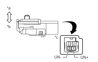
2.208,2.021 2.333,2.021
2.333,2.021 2.406,1.74
true
2.74,2.021 2.615,2.021
2.615,2.021 2.573,1.74
true
0.24,0.198 0.479,0.385
0.24,0.188
10
false
*a
0.24,0.854 0.458,1.01
0.219,0.156
10
false
*b
1.917,1.229 2.156,1.417
0.24,0.188
10
false
*c
2.823,1.938 3.281,2.125
0.458,0.188
10
false
UN+
1.906,1.927 2.365,2.115
0.458,0.188
10
false
UN-
| *a | Switch not pushed |
| *b | Switch pushed |
| *c | Component without harness connected
(Unlock Warning Switch Assembly) |
a.
Measure the resistance according to the value(s) in the table below.
- Standard Resistance:
Tester Connection Switch Condition Specified Condition 1 (UN+) - 2 (UN-) Switch not pushed
(Key removed)10 kΩ or higher 1 (UN+) - 2 (UN-) Switch pushed
(Key inserted)Below 1 Ω
If the result is not as specified, replace the unlock warning switch assembly.