AUDIO / VIDEO AUDIO AND VISUAL SYSTEM(for Radio and Display Type) B157D DAB Tuner Antenna Disconnected
DESCRIPTION
This DTC is stored when a malfunction occurs in the DAB tuner antenna which is connected to the radio and display receiver assembly.
| DTC No. | Detection Item | DTC Detection Condition | Trouble Area |
|---|---|---|---|
| B157D | DAB Tuner Antenna Disconnected | The DAB tuner antenna is not connected | ·
Windshield Glass (DAB Antenna) ·
No. 2 Antenna cord sub-assembly ·
Antenna cord sub-assembly ·
Radio and display receiver assembly |
WIRING DIAGRAM
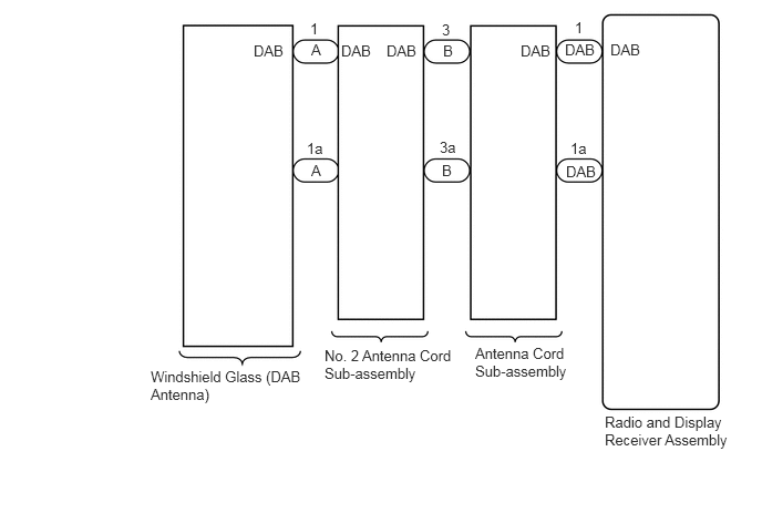
CAUTION / NOTICE / HINT
- NOTICE:
- ·
Check that the wire harness is properly installed and does not have any sharp bends, pinching or loose connections.
·When replacing the radio and display receiver assembly, always replace it with a new one. If a radio and display receiver assembly which was installed to another vehicle is used, the following may occur:
-A communication malfunction DTC may be stored.
-The radio and display receiver assembly may not operate normally.
- HINT:
-
Depending on the parts that are replaced during vehicle inspection or maintenance, performing initialization, registration or calibration may be needed. Refer to Precaution for Audio and Visual System.
PROCEDURE
Clear the DTCs.
- Body Electrical > Navigation System > Clear DTCs
- 50002 212
Check for DTCs.
- Body Electrical > Navigation System > Trouble Codes
- 50001 212
- OK:
No DTCs are output.
- Result:
Proceed to OK NG
OK
NG
Check if any optional components that may decrease reception capacity, such as a telephone antenna, are installed.
- OK:
Optional components are installed.
- NOTICE:
-
Do not remove optional components without permission of the customer.
- Result:
Proceed to OK NG
OK
NG
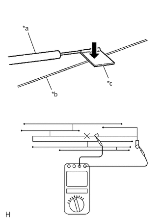
| *a | Tester Probe |
| *b | Antenna Wire |
| *c | Tin Foil |
Check for continuity in the windshield glass antenna wire.
- HINT:
-
Check for continuity at the center of each antenna wire as shown in the illustration.
- NOTICE:
-
When cleaning the glass, wipe it in the direction of the wire with a soft dry cloth. Take care not to damage the wire. Do not use detergents or glass cleaners with abrasive ingredients. When measuring resistance, wrap a piece of tin foil around the tip of each probe and press the foil against the wire with your finger as shown in the illustration.
- OK:
There is continuity in the door glass antenna wire.
- Result:
Proceed to OK NG
OK
NG
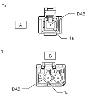
| *a | Front view of wire harness connector
(to Antenna Cord Sub-assembly) |
| *b | Front view of wire harness connector
(to Windshield Glass [DAB Antenna]) |
Disconnect the antenna connector from the antenna cord sub-assembly.
Disconnect the antenna connector from the windshield glass (DAB Antenna).
Measure the resistance according to the value(s) in the table below.
- Standard Resistance:
Tester Connection Condition Specified Condition B-3 (DAB) - A-1 (DAB) Always Below 1 Ω B-3a - A-1a Always Below 1 Ω B-3 (DAB) - Body ground Always 10 kΩ or higher
- Result:
Proceed to OK NG
OK
NG
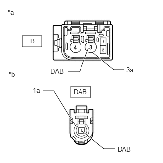
| *a | Front view of wire harness connector
(to No. 2 Antenna Cord Sub-assembly) |
| *b | Front view of wire harness connector
(to Radio and Display Receiver Assembly) |
Disconnect the antenna connector from the radio and display receiver assembly.
Disconnect the antenna connector from the No. 2 antenna cord sub-assembly.
Measure the resistance according to the value(s) in the table below.
- Standard Resistance:
Tester Connection Condition Specified Condition DAB-1 (DAB) - B-3 (DAB) Always Below 1 Ω DAB-1a - B-3a Always Below 1 Ω DAB-1 (DAB) - Body ground Always 10 kΩ or higher
- Result:
Proceed to OK NG
OK
NG
Replace the windshield glass (DAB Antenna) with a new or known good one.
Clear the DTCs.
- Body Electrical > Navigation System > Clear DTCs
- 50002 212
Recheck for DTCs and check that no DTCs are output.
- Body Electrical > Navigation System > Trouble Codes
- 50001 212
- OK:
No DTCs are output.
- Result:
Proceed to OK NG
OK
NG