BRAKE CONTROL / DYNAMIC CONTROL SYSTEMS ELECTRONICALLY CONTROLLED BRAKE SYSTEM(w/ VSC OFF Switch) Brake Warning Light Remains ON
DESCRIPTION
This procedure is for troubleshooting when the brake warning light remains on but no DTCs are output.
The skid control ECU (brake actuator assembly) controls the brake warning light in the combination meter assembly via CAN communication.
WIRING DIAGRAM
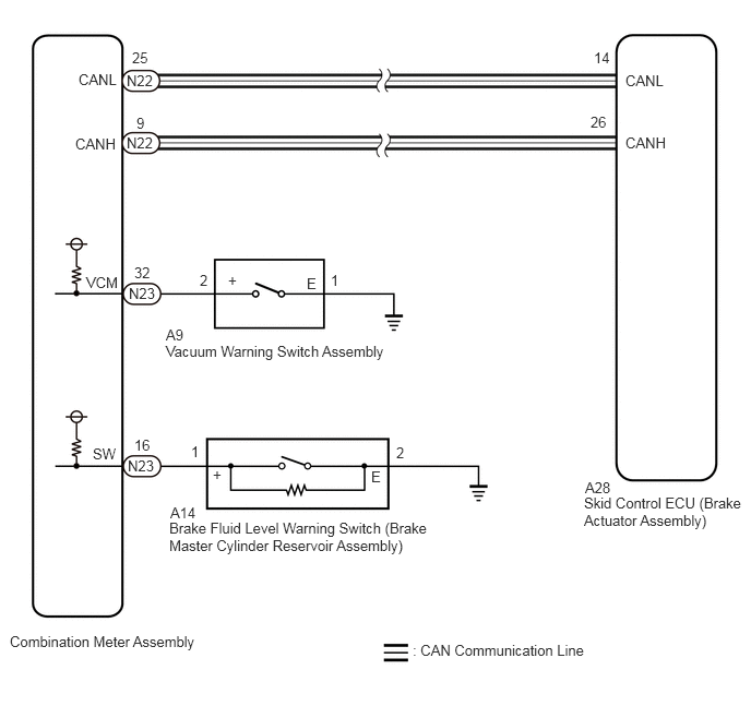
CAUTION / NOTICE / HINT
- NOTICE:
- ·
After replacing the skid control ECU (brake actuator assembly), perform acceleration sensor zero point calibration and store system information memorization.
·Before performing this procedure, depress the brake pedal and confirm that the stop lights illuminate.
PROCEDURE
Check that all of the following conditions required for the brake warning light to turn off are met:
The ABS warning light is not illuminated.
- HINT:
-
If the ABS warning light remains illuminated, make sure that the conditions required for the ABS warning light to turn off are met.
The brake fluid level in the brake master cylinder reservoir assembly is not low.
The vacuum inside the brake booster decreases.
- HINT:
-
When the vacuum inside the brake booster decreases, the brake warning light comes on.
- Result:
Proceed to NEXT
NEXT
Connect the GTS to the DLC3.
Turn the ignition switch to ON.
Enter the following menus: Chassis / Brake / Utility / Vehicle Control History (RoB).
Using the GTS, check for Vehicle Control History.
- Chassis > Brake > Utility
-
Tester Display Vehicle Control History (RoB) - 50005 435 1055
- HINT:
-
If vehicle control history is stored when the electronically controlled brake system is suspended, the brake warning light illuminates.
- Result:
Result Proceed to There is no vehicle control history for when the electronically controlled brake system was suspended. A There is vehicle control history for when the electronically controlled brake system was suspended. B
A
B
- NOTICE:
-
After performing troubleshooting and repair regarding vehicle control history, clear the vehicle control history.
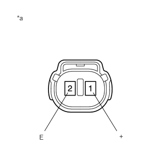
| *a | Component without harness connected
(Brake Fluid Level Warning Switch (Brake Master Cylinder Reservoir Assembly)) |
Make sure that there is no looseness at the locking part and the connecting part of the connector.
- OK:
The connector is securely connected.
Disconnect the A14 brake fluid level warning switch (brake master cylinder reservoir assembly) connector.
Check both the connector case and the terminals for deformation and corrosion.
- OK:
No deformation or corrosion.
Measure the resistance according to the value(s) in the table below.
- HINT:
-
A float is located inside the reservoir. Its position changes according to the brake fluid level.
- Standard Resistance:
Tester Connection Condition Specified Condition 1 (+) - 2 (E) Switch off (float up) 1.9 to 2.1 kΩ 1 (+) - 2 (E) Switch on (float down) Below 1 Ω
If there is no problem after finishing the above check, adjust the brake fluid level to the MAX level.
- Result:
Proceed to OK NG
OK
NG
for LHD: Click hereBrake>BRAKE SYSTEM (OTHER)>BRAKE MASTER CYLINDER (for LHD)>DISASSEMBLY201902,999999,_54,_078668,_0381536,RM100000001G0KP,
for RHD: Click hereBrake>BRAKE SYSTEM (OTHER)>BRAKE MASTER CYLINDER (for RHD)>DISASSEMBLY201902,999999,_54,_078668,_0381537,RM100000001G0KW,
Make sure that there is no looseness at the locking part and the connecting part of the connector.
- OK:
The connector is securely connected.
Disconnect the N23 combination meter assembly connector.
Disconnect the A14 brake fluid level warning switch (brake master cylinder reservoir assembly) connector.
Check both the connector case and the terminals for deformation and corrosion.
- OK:
No deformation or corrosion.
Measure the resistance according to the value(s) in the table below.
- Standard Resistance:
Tester Connection Condition Specified Condition N23-16 (SW) - A14-1 (+) Always Below 1 Ω N23-16 (SW) or A14-1 (+) - Body ground Always 10 kΩ or higher A14-2 (E) - Body ground Always Below 1 Ω
- Result:
Proceed to OK NG
OK
NG
Inspect the vacuum warning switch assembly.
for LHD: Click hereBrake>BRAKE SYSTEM (OTHER)>VACUUM WARNING SWITCH (for LHD)>ON-VEHICLE INSPECTION201902,999999,_54,_078668,_0390191,RM100000001HDVN,
for RHD: Click hereBrake>BRAKE SYSTEM (OTHER)>VACUUM WARNING SWITCH (for RHD)>ON-VEHICLE INSPECTION201902,999999,_54,_078668,_0381540,RM100000001G0LG,
- OK:
The vacuum warning switch assembly is normal.
- Result:
Proceed to OK NG
OK
NG
for LHD: Click hereBrake>BRAKE SYSTEM (OTHER)>VACUUM WARNING SWITCH (for LHD)>REMOVAL201902,999999,_54,_078668,_0390191,RM100000001HDVO,
for RHD: Click hereBrake>BRAKE SYSTEM (OTHER)>VACUUM WARNING SWITCH (for RHD)>REMOVAL201902,999999,_54,_078668,_0381540,RM100000001G0LE,
Make sure that there is no looseness at the locking part and the connecting part of the connector.
- OK:
The connector is securely connected.
Disconnect the N23 combination meter assembly connector.
Disconnect the A9 vacuum warning switch assembly connector.
Check both the connector case and the terminals for deformation and corrosion.
- OK:
No deformation or corrosion.
Measure the resistance according to the value(s) in the table below.
- Standard Resistance:
Tester Connection Condition Specified Condition N23-32 (VCM) - A9-2 (+) Always Below 1 Ω N23-32 (VCM) or A9-2 (+) - Body ground Always 10 kΩ or higher A9-1 (E) - Body ground Always Below 1 Ω
- Result:
Proceed to OK NG
OK
NG
Connect the GTS to the DLC3.
Turn the ignition switch to ON.
Enter the following menus: Body Electrical / Combination Meter / Active Test.
Perform the Active Test of the combination meter assembly using the GTS.
- Body Electrical > Combination Meter > Active Test
-
Tester Display Brake Warning - 50004 409 107
Check the combination meter assembly.
- OK:
The brake warning light turns on or off in accordance with the GTS operation.
- Result:
Proceed to OK NG
OK
NG