7GR-FKS ENGINE CONTROL SFI SYSTEM P244072 AIR System Switching Valve Stuck Open Bank 1 Actuator Stuck Open P244173 AIR System Switching Valve Stuck Closed Bank 1 Actuator Stuck Closed P244272 AIR System Switching Valve Stuck Open Bank 2 Actuator Stuck Open P244373 AIR System Switching Valve Stuck Closed Bank 2 Actuator Stuck Closed
DESCRIPTION
Refer to DTC P041211.
| DTC No. | Detection Item | DTC Detection Condition | Trouble Area | MIL | Memory | Note |
|---|---|---|---|---|---|---|
| P244072 | AIR System Switching Valve Stuck Open Bank 1 Actuator Stuck Open | Either of the following conditions is met (1 trip detection logic):
·
The pressure sensor detects a pulsation in the exhaust gas despite the ECM commanding the emission control valve to close while the engine is running. ·
When secondary air injection is off, the cumulative pressure pulsation exceeds the threshold. |
·
Emission control valve (for bank 1) ·
Open or short in emission control valve (for bank 1) circuit ·
Secondary air injection system piping ·
Pressure sensor (for bank 1) ·
Pressure sensor (for bank 1) circuit ·
Air injection control driver ·
ECM |
Comes on | DTC stored | SAE Code: P2440 |
| P244173 | AIR System Switching Valve Stuck Closed Bank 1 Actuator Stuck Closed | Either of the following conditions is met (2 trip detection logic):
·
The pressure sensor detects no pulsation in the exhaust gas despite the ECM commanding the emission control valve to open while the engine is running. ·
When secondary air injection is turned on (when only the emission control valve for bank 2 is closed), there is no exhaust gas pulsation. |
·
Emission control valve (for bank 1) ·
Open or short in emission control valve (for bank 1) circuit ·
Secondary air injection system piping ·
Pressure sensor (for bank 1) ·
Pressure sensor (for bank 1) circuit ·
Air injection control driver ·
ECM |
Comes on | DTC stored | SAE Code: P2441 |
| P244272 | AIR System Switching Valve Stuck Open Bank 2 Actuator Stuck Open | One of the following conditions is met (1 trip detection logic):
·
The pressure sensor detects a pulsation in the exhaust gas despite the ECM commanding the emission control valve to close while the engine is running. ·
When secondary air injection is turned on (when only the emission control valve for bank 2 is open), there is no change in the secondary air injection pressure. ·
When secondary air injection is off, the cumulative pressure pulsation exceeds the threshold. |
·
Emission control valve (for bank 2) ·
Open or short in emission control valve (for bank 2) circuit ·
Secondary air injection system piping ·
Pressure sensor (for bank 2) ·
Pressure sensor (for bank 2) circuit ·
AI VALVE relay ·
ECM |
Comes on | DTC stored | SAE Code: P2442 |
| P244373 | AIR System Switching Valve Stuck Closed Bank 2 Actuator Stuck Closed | Either of the following conditions is met (2 trip detection logic):
·
The pressure sensor detects no pulsation in the exhaust gas despite the ECM commanding the emission control valve to open while the engine is running. ·
When secondary air injection is turned on (when only the emission control valve for bank 2 is open), there is no change in the secondary air injection pressure. |
·
Emission control valve (for bank 2) ·
Open or short in emission control valve (for bank 2) circuit ·
Secondary air injection system piping ·
Pressure sensor (for bank 2) ·
Pressure sensor (for bank 2) circuit ·
AI VALVE relay ·
ECM |
Comes on | DTC stored | SAE Code: P2443 |
- HINT:
-
Emission control valve normal operation:
-
When the emission control valve is open, exhaust gas pulsation occurs in the secondary air passage.
-
When the emission control valve is closed, exhaust gas pulsation does not occur in the secondary air passage.
MONITOR DESCRIPTION
DTCs P244072 and P244272 indicate that the emission control valve set is stuck open. DTCs P244173 and P244373 indicate that the emission control valve set is stuck closed. The ECM performs diagnosis of the secondary air injection system based on the changes in pressure and the pressure pulsation. If a malfunction is detected, the ECM illuminates the MIL and stores a DTC.
CONFIRMATION DRIVING PATTERN
- NOTICE:
- ·
This Secondary Air Injection Check only allows technicians to operate the secondary air injection system for a maximum of 5 seconds. Furthermore, the check can only be performed up to 4 times per trip. If the test is repeated, intervals of at least 30 seconds are required between checks. While secondary air injection system operation using the GTS is prohibited, the GTS display indicates the prohibition (WAIT or ERROR). If ERROR is displayed on the GTS during the test, stop the engine for 10 minutes, and then try again.
·Performing the Secondary Air Injection Check repeatedly may cause damage to the secondary air injection system. If necessary, leave an interval of several minutes between System Check operations to prevent the system from overheating.
·When performing the Secondary Air Injection Check operation after the battery cable has been reconnected, wait for 7 minutes with the ignition switch turned to ON or the engine running.
·Turn the ignition switch off when the Secondary Air Injection Check operation finishes.
Start the engine and warm it up.
Turn the ignition switch off.
Connect the GTS to the DLC3.
Turn the ignition switch to ON.
Turn the GTS on.
Clear DTCs (even if no DTCs are stored, perform the clear DTC operation).
Turn the ignition switch off and wait for at least 30 seconds.
Turn the ignition switch to ON and turn the GTS on.
Enter the following menus: Powertrain / Engine / Utility / Secondary Air Injection Check / Automatic Mode.
Start the engine after the GTS initialization is finished.
Perform the System Check operation by pressing Next.
Perform the following to confirm the secondary air injection system pending DTCs: Press the Exit.
Enter the following menus: Powertrain / Engine / DTC.
Read pending DTCs.
- HINT:
- ·
If a pending DTC is output, the system is malfunctioning.
·If a pending DTC is not output, perform the following procedure.
After Secondary Air Injection Check is completed, check All Readiness by entering the following menus: Powertrain / Engine / Utility / All Readiness.
Input the DTC: P244072, P244173, P244272 or P244373.
Check the DTC judgment result.
| GTS Display | Description |
|---|---|
| NORMAL | ·
DTC judgment completed ·
System normal |
| ABNORMAL | ·
DTC judgment completed ·
System abnormal |
| INCOMPLETE | ·
DTC judgment not completed ·
Perform driving pattern after confirming DTC enabling conditions |
- HINT:
- ·
If the judgment result shows NORMAL, the system is normal.
·If the judgment result shows ABNORMAL, the system has a malfunction.
·If the judgment result shows INCOMPLETE, perform the Confirmation Driving Pattern and the DTC judgment result again.
WIRING DIAGRAM
Refer to DTC P041211.
Refer to DTC P041512.
CAUTION / NOTICE / HINT
- HINT:
- ·
Refer to "Data List / Active Test" [Air Pump Pulsation Pressure Bank 1, Air Pump Pulsation Pressure Bank 2, Air Pump Pressure (Absolute) Bank 1 and Air Pump Pressure (Absolute) Bank 2].
·By using the GTS to perform the Secondary Air Injection Check operation in the System Check, the air fuel ratio and the pressure in the secondary air injection system passage can be checked while the secondary air injection system is operating. This helps technicians to troubleshoot the system when it malfunctions.
·Bank 1 refers to the bank that includes the No. 1 cylinder*.
*: The No. 1 cylinder is the cylinder which is farthest from the transmission.
·Bank 2 refers to the bank that does not include the No. 1 cylinder.
·Read Freeze Frame Data using the GTS. The ECM records vehicle and driving condition information as Freeze Frame Data the moment a DTC is stored. When troubleshooting, Freeze Frame Data can help determine if the vehicle was moving or stationary, if the engine was warmed up or not, if the air fuel ratio was lean or rich, and other data from the time the malfunction occurred.
PROCEDURE
Connect the GTS to the DLC3.
Turn the ignition switch to ON.
Turn the GTS on.
Enter the following menus: Powertrain / Engine / DTC.
Read DTCs and freeze frame data.
- Powertrain > Engine > Trouble Codes
- 50001 372
- Result:
Result Proceed to P244072, P244173, P244272 and/or P244373 is output A P244072 and/or P244173 and P041211 and/or P041215 are output B P244272 and/or P244373 and P041512 and/or P041514 are output C P244072, P244173, P244272 and/or P244373 and other DTCs (except P041211, P041215, P041512 and P041514) are output D
- HINT:
-
If any DTCs other than P041211, P041215, P041512, P041514, P244072, P244173, P244272 and P244373 are output, troubleshoot those DTCs first.
A
B
C
D
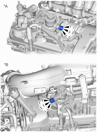
| *A | Bank 1 |
| *B | Bank 2 |
Perform a visual check:
Start the engine and warm it up.
Turn the ignition switch off.
Disconnect the air hoses.
Connect the GTS to the DLC3.
Turn the ignition switch to ON.
Turn the GTS on.
Enter the following menus: Powertrain / Engine / Utility / Secondary Air Injection Check / Manual Mode / AIR PUMP: ON, ASV 1: OPEN, ASV 2: OPEN.
- Powertrain > Engine > Utility
-
Tester Display Secondary Air Injection Check - 50005 372 26
- HINT:
-
When Manual Mode is selected, the GTS initialization (atmospheric pressure measurement) is performed automatically. The initialization takes 5 seconds. After the initialization, AIR PUMP and ASV operation can be selected.
Start the engine.
Perform the secondary air injection system forced operation while the engine is idling.
Place your hand near the emission control valve port and check that the exhaust gas pressure pulsates when the emission control valve is turned on.
- CAUTION:
-
To avoid the danger of being burned by the exhaust gas, bring your hand close to the valve port slowly.
Enter the following menus: Powertrain / Engine / Utility / Secondary Air Injection Check / Manual Mode / AIR PUMP: ON, ASV 1: OPEN, ASV 2: OPEN and AIR PUMP: ON, ASV 1: CLOSE, ASV 2: CLOSE.
- Powertrain > Engine > Utility
-
Tester Display Secondary Air Injection Check - 50005 372 26
Check that the exhaust gas does not pulsate when the emission control valve is turned off.
Turn the ignition switch off.
- NOTICE:
- ·
This Secondary Air Injection Check only allows technicians to operate the secondary air injection system for a maximum of 5 seconds. Furthermore, the check can only be performed up to 4 times per trip. If the test is repeated, intervals of at least 30 seconds are required between checks. While secondary air injection system operation using the GTS is prohibited, the GTS display indicates the prohibition (WAIT or ERROR). If ERROR is displayed on the GTS during the test, stop the engine for 10 minutes, and then try again.
·Performing the Secondary Air Injection Check repeatedly may cause damage to the secondary air injection system. If necessary, leave an interval of several minutes between System Check operations to prevent the system from overheating.
·When performing the Secondary Air Injection Check operation after the battery cable has been reconnected, wait for 7 minutes with the ignition switch turned to ON or the engine running.
·Turn the ignition switch off when the Secondary Air Injection Check operation finishes.
- OK:
Air Pump Operation Emission Control Valve Operation Exhaust Gas Pulsation ON OFF Not detected ON ON Detected
- Result:
Result OK NG
OK
NG
Connect the GTS to the DLC3.
Turn the ignition switch to ON.
Turn the GTS on.
Enter the following menus: Powertrain / Engine / Data List / Air Pump Pressure (Absolute) Bank 1 and Air Pump Pressure (Absolute) Bank 2.
Check the pressure displayed on the GTS.
- Standard pressure:
45.6 to 135 kPa (6.612 to 19.575 psi)
- HINT:
-
The GTS displays the air pump pressure as absolute pressure.
- Result:
Result Proceed to OK A NG B
A
B
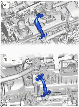
| *A | Bank 1 |
| *B | Bank 2 |
Check that the air tubes are securely connected to both the exhaust manifold and the emission control valve set.
Inspect the air tube for blockages and damage.
- OK:
No blockages in or damage to air tubes.
- Result:
Result OK NG
OK
NG
Inspect the emission control valve set.
- Result:
Result Proceed to OK A NG B
A
B
- Result:
Result OK NG
OK
NG
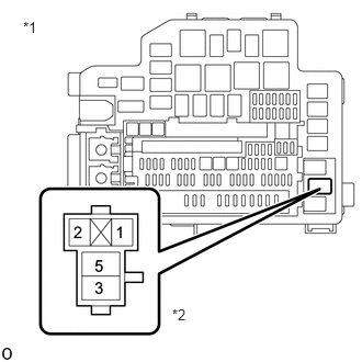
| *1 | No. 1 Engine Room Relay Block and Junction Block Assembly |
| *2 | AI VALVE relay |
Remove the AI VALVE relay from the No. 1 engine room relay block and junction block assembly.
Measure the voltage according to the value(s) in the table below.
- Standard Voltage:
Tester Connection Condition Specified Condition 1 (AI VALVE relay) - Body ground Ignition switch ON 11 to 14 V 3 (AI VALVE relay) - Body ground Always 11 to 14 V
- Result:
Result OK NG
OK
NG
Remove the AI VALVE relay from the No. 1 engine room relay block and junction block assembly.
Disconnect the ECM connector.
Measure the resistance according to the value(s) in the table below.
- Standard Resistance:
Tester Connection Condition Specified Condition 2 (AI VALVE relay) - A1-6 (AIR1) Always Below 1 Ω 2 (AI VALVE relay) or A1-6 (AIR1) - Body ground and other terminals Always 10 kΩ or higher
- Result:
Result OK NG
OK
NG
Disconnect the emission control valve set (for bank 2) connector.
Remove the AI VALVE relay from the No. 1 engine room relay block and junction block assembly.
Measure the resistance according to the value(s) in the table below.
- Standard Resistance:
Tester Connection Condition Specified Condition E31-5 (+BL) - 5 (AI VALVE relay) Always Below 1 Ω E31-1 (GNDL) - Body ground Always Below 1 Ω E31-5 (+BL) or 5 (AI VALVE relay) - Body ground and other terminals Always 10 kΩ or higher
- Result:
Result OK NG
OK
NG
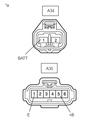
| *a | Front view of wire harness connector
(to Air Injection Control Driver) |
Disconnect the air injection control driver connectors.
Measure the resistance according to the value(s) in the table below.
- Standard Resistance:
Tester Connection Condition Specified Condition A35-1 (E) - Body ground Always Below 1 Ω
Turn the ignition switch to ON.
Measure the voltage according to the value(s) in the table below.
- Standard Voltage:
Tester Connection Switch Condition Specified Condition A34-1 (BATT) - Body ground Always 11 to 14 V (near battery voltage) A35-5 (+B) - Body ground Ignition switch ON 11 to 14 V (near battery voltage)
- Result:
Result OK NG
OK
NG
Disconnect the ECM connectors.
Disconnect the air injection control driver connectors.
Measure the resistance according to the value(s) in the table below.
- Standard Resistance:
Tester Connection Condition Specified Condition A1-14 (AIRV) - A35-3 (SIV) Always Below 1 Ω A1-14 (AIRV) or A35-3 (SIV) - Body ground and other terminals Always 10 kΩ or higher
- Result:
Result OK NG
OK
NG
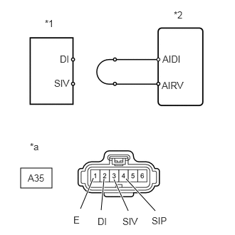
| *1 | Air Injection Control Driver |
| *2 | ECM |
| *a | Front view of wire harness connector
(to Air Injection Control Driver) |
Disconnect the air injection control driver connector.
Connect terminals DI and SIV of the wire harness connector for the air injection control driver.
Connect the GTS to the DLC3.
Turn the ignition switch to ON and turn the GTS on.
Enter the following menus: Powertrain / Engine / Utility / Secondary Air Injection Check / Manual Mode / AIR PUMP: ON, ASV 1: OPEN, ASV 2: OPEN.
- Powertrain > Engine > Utility
-
Tester Display Secondary Air Injection Check - 50005 372 26
- HINT:
-
When Manual Mode is selected, the GTS initialization (atmospheric pressure measurement) is performed automatically. The initialization takes 5 seconds. After the initialization, AIR PUMP and ASV operation can be selected.
Start the engine.
Perform the secondary air injection system forced operation while the engine is idling.
Measure the voltage between the SIV and E terminals of the ECM connector when the Secondary air injection system is ON and OFF.
Turn the ignition switch off.
- NOTICE:
- ·
Do not perform the System Check operation repeatedly as it may cause the damage in the system. If necessary, leave an interval of several minutes between System Check operations.
·When performing the Secondary Air Injection Check operation after the battery cable has been reconnected, wait for 7 minutes with the ignition switch turned to ON or the engine running.
·Turn the ignition switch off when the Secondary Air Injection Check operation finishes.
- Standard Voltage:
Tester Connection Condition Specified Condition A35-3 (SIV) - A35-1 (E) AIR PUMP: ON, ASV 1: OPEN, ASV 2: OPEN 0.5 to 2 V AIR PUMP: OFF, ASV 1: CLOSE, ASV 2: CLOSE 11 to 14 V
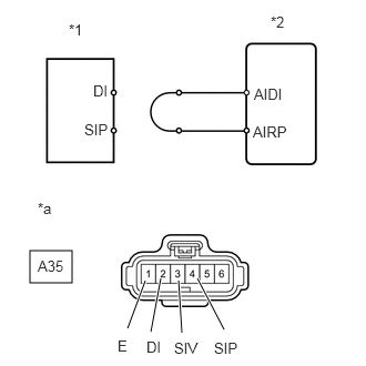
| *1 | Air Injection Control Driver |
| *2 | ECM |
| *a | Front view of wire harness connector
(to Air Injection Control Driver) |
Connect terminals DI and SIP of the wire harness connector for the air injection control driver.
Connect the GTS to the DLC3.
Turn the ignition switch to ON.
Turn the GTS on.
Enter the following menus: Powertrain / Engine / Utility / Secondary Air Injection Check / Manual Mode / AIR PUMP: ON, ASV 1: OPEN, ASV 2: OPEN.
- Powertrain > Engine > Utility
-
Tester Display Secondary Air Injection Check - 50005 372 26
- HINT:
-
When Manual Mode is selected, the GTS initialization (atmospheric pressure measurement) is performed automatically. The initialization takes 5 seconds. After the initialization, AIR PUMP and ASV operation can be selected.
Start the engine.
Perform the secondary air injection system forced operation while the engine is idling.
Measure the voltage between the SIP and E terminals of the ECM connector when the secondary air injection system is ON and OFF.
Turn the ignition switch off.
- NOTICE:
- ·
Do not perform the System Check operation repeatedly as it may cause the damage in the system. If necessary, leave an interval of several minutes between System Check operations.
·When performing the Secondary Air Injection Check operation after the battery cable has been reconnected, wait for 7 minutes with the ignition switch turned to ON or the engine running.
·Turn the ignition switch off when the Secondary Air Injection Check operation finishes.
- Standard Voltage:
Tester Connection Condition Specified Condition A35-4 (SIP) - A35-1 (E) AIR PUMP: ON, ASV 1: OPEN, ASV 2: OPEN 0.5 to 2 V AIR PUMP: OFF, ASV 1: CLOSE, ASV 2: CLOSE 11 to 14 V
- Result:
Result OK NG
OK
NG
Replace the air injection control driver.
- Result:
Result NEXT
NEXT
Connect the GTS to the DLC3.
Turn the ignition switch to ON.
Turn the GTS on.
Clear the DTC.
- Powertrain > Engine > Clear DTCs
- 50002 372
Turn the ignition switch off and wait for at least 30 seconds.
- Result:
Proceed to NEXT
NEXT
Start the engine and warm it up.
Turn the ignition switch off.
Turn the ignition switch to ON.
Turn the GTS on.
Enter the following menus: Powertrain / Engine / Utility / Secondary Air Injection Check / Automatic Mode.
- Powertrain > Engine > Utility
-
Tester Display Secondary Air Injection Check - 50005 372 26
Start the engine after the GTS initialization is finished.
Perform the System Check operation by pressing Next.
Perform the following to confirm the secondary air injection system pending DTCs: Press the Exit.
Enter the following menus: Powertrain / Engine / Trouble Codes.
Read pending DTCs.
- OK:
No pending DTC is output.
Turn the ignition switch off.
- NOTICE:
- ·
When performing the Secondary Air Injection Check operation after the battery cable has been reconnected, wait for 7 minutes with the ignition switch turned to ON or the engine running.
·Turn the ignition switch off when the Secondary Air Injection Check operation finishes.
- Result:
Result OK NG
OK
NG