7GR-FKS ENGINE CONTROL RELAY ON-VEHICLE INSPECTION
PROCEDURE

 82641
1.INSPECT NO. 1 INTEGRATION RELAY
82641
1.INSPECT NO. 1 INTEGRATION RELAY

| *a | Component without harness connected
(No. 1 Integration Relay) |
- | - |
- NOTICE:
- ·
The IG2 MAIN relay, EFI MAIN relay, INJ relay, A/F relay and EFI MAIN NO. 2 relay are built into the No. 1 integration relay.
·Before performing the relay inspections for the relays of the No. 1 integration relay, inspect the IG2-MAIN, EFI-MAIN, A/F and EFI-MAIN NO. 2 fuses.
Inspect the IG2 MAIN relay.
Inspect the IG2-MAIN fuse.
Measure the resistance according to the value(s) in the table below.
- Standard Resistance:
Tester Connection Condition Specified Condition 1D-1 - A-1 Battery voltage not applied to terminals 1D-2 and 1E-4 10 kΩ or higher Battery voltage applied to terminals 1D-2 and 1E-4 Below 1 Ω
If the result is not as specified, replace the No. 1 integration relay.
Inspect the EFI MAIN relay.
Inspect the EFI-MAIN fuse.
Measure the resistance according to the value(s) in the table below.
- Standard Resistance:
Tester Connection Condition Specified Condition A-1 - 1E-10 Battery voltage not applied to terminals 1E-4 and 1E-8 10 kΩ or higher Battery voltage applied to terminals 1E-4 and 1E-8 Below 1 Ω
If the result is not as specified, replace the No. 1 integration relay.
Inspect the INJ relay.
Measure the resistance according to the value(s) in the table below.
- Standard Resistance:
Tester Connection Condition Specified Condition 1B-1 - 1B-3 Battery voltage not applied to terminals 1B-6 and 1C-4 10 kΩ or higher Battery voltage applied to terminals 1B-6 and 1C-4 Below 1 Ω
If the result is not as specified, replace the No. 1 integration relay.
Inspect the A/F relay.
Inspect the A/F fuse.
Measure the resistance according to the value(s) in the table below.
- Standard Resistance:
Tester Connection Condition Specified Condition 1E-3 - A-1 Battery voltage not applied to terminals 1E-1 and 1E-4 10 kΩ or higher Battery voltage applied to terminals 1E-1 and 1E-4 Below 1 Ω
If the result is not as specified, replace the No. 1 integration relay.
Inspect the EFI MAIN NO. 2 relay.
Inspect the EFI MAIN-NO. 2 fuse.
Measure the resistance according to the value(s) in the table below.
- Standard Resistance:
Tester Connection Condition Specified Condition 1D-6 - A-1 Battery voltage not applied to terminals 1D-7 and 1E-10 10 kΩ or higher Battery voltage applied to terminals 1D-7 and 1E-10 Below 1 Ω
If the result is not as specified, replace the No. 1 integration relay.
89589B
2.INSPECT AI VALVE RELAY (w/ Secondary Air Injection System)
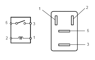
Measure the resistance according to the value(s) in the table below.
- Standard Resistance:
Tester Connection Condition Specified Condition 3 - 5 Battery voltage not applied to terminals 1 and 2 10 kΩ or higher Battery voltage applied to terminals 1 and 2 Below 1 Ω
If the result is not as specified, replace the AI VALVE relay.