7GR-FKS EMISSION CONTROL AIR SWITCHING VALVE(w/ Secondary Air Injection System) INSPECTION
PROCEDURE

 25701B
1.INSPECT AIR SWITCHING VALVE ASSEMBLY (for RH Side)
25701B
1.INSPECT AIR SWITCHING VALVE ASSEMBLY (for RH Side)
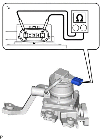
| *a | Component without harness connected
(Air Switching Valve Assembly) |
Measure the resistance according to the value(s) in the table below.
- Standard Resistance:
Tester Connection Condition Specified Condition 1 - 5 20°C (68°F)* 4.5 to 5.5 Ω 1 - Body ground Always 1 MΩ or higher 5 - Body ground
- NOTICE:
-
When applying voltage, do not touch terminals 2, 3 and 4.
- HINT:
-
*: Make sure that the air switching valve assembly is at ambient temperature before measuring the resistance.
If the result is not as specified, replace the air switching valve assembly.
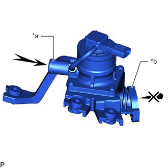
| *a | Port A |
| *b | Port B |
Check the operation of the air switching valve assembly.
Check that air does not flow from port A to port B.
- NOTICE:
-
Make sure the applied pressure is 30 kPa (0.3 kgf/cm2, 4.4 psi) or less.
If the result is not as specified, replace the air switching valve assembly.
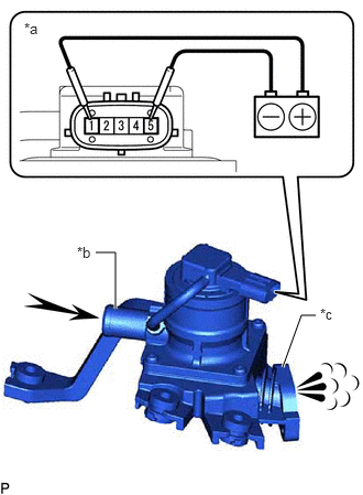
| *a | Component without harness connected
(Air Switching Valve Assembly) |
| *b | Port A |
| *c | Port B |
Apply battery voltage across terminals 1 and 5.
- NOTICE:
-
When applying voltage, do not touch terminals 2, 3 and 4.
Check that air flows from port A to port B.
If the result is not as specified, replace the air switching valve assembly.
25702B
2.INSPECT AIR SWITCHING VALVE ASSEMBLY (for LH Side)
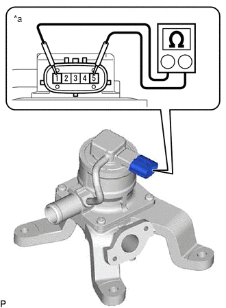
| *a | Component without harness connected
(Air Switching Valve Assembly) |
Measure the resistance according to the value(s) in the table below.
- Standard Resistance:
Tester Connection Condition Specified Condition 1 - 5 20°C (68°F)* 4.5 to 5.5 Ω 1 - Body ground Always 1 MΩ or higher 5 - Body ground
- NOTICE:
-
When applying voltage, do not touch terminals 2, 3 and 4.
- HINT:
-
*: Make sure that the air switching valve assembly is at ambient temperature before measuring the resistance.
If the result is not as specified, replace the air switching valve assembly.
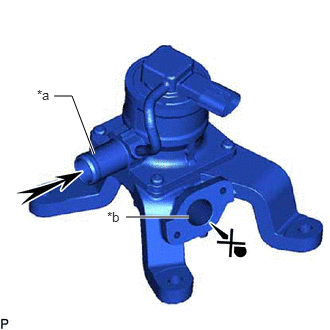
| *a | Port A |
| *b | Port B |
Check the operation of the air switching valve assembly.
Check that air does not flow from port A to port B.
- NOTICE:
-
Make sure the applied pressure is 30 kPa (0.3 kgf/cm2, 4.4 psi) or less.
If the result is not as specified, replace the air switching valve assembly.
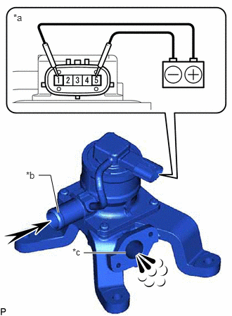
| *a | Component without harness connected
(Air Switching Valve Assembly) |
| *b | Port A |
| *c | Port B |
Apply battery voltage across terminals 1 and 5.
- NOTICE:
-
When applying voltage, do not touch terminals 2, 3 and 4.
Check that air flows from port A to port B.
If the result is not as specified, replace the air switching valve assembly.