7GR-FKS ENGINE CONTROL SFI SYSTEM P219519 A/F (O2) Sensor Signal Biased/Stuck Lean Bank 1 Sensor 1 Circuit Current Above Threshold P219524 A/F (O2) Sensor Signal Biased/Stuck Lean Bank 1 Sensor 1 Signal Stuck High P219618 A/F (O2) Sensor Signal Biased/Stuck Rich Bank 1 Sensor 1 Circuit Current Below Threshold P219623 A/F (O2) Sensor Signal Biased/Stuck Rich Bank 1 Sensor 1 Signal Stuck Low P219719 A/F (O2) Sensor Signal Biased/Stuck Lean Bank 2 Sensor 1 Circuit Current Above Threshold P219724 A/F (O2) Sensor Signal Biased/Stuck Lean Bank 2 Sensor 1 Signal Stuck High P219818 A/F (O2) Sensor Signal Biased/Stuck Rich Bank 2 Sensor 1 Circuit Current Below Threshold P219823 A/F (O2) Sensor Signal Biased/Stuck Rich Bank 2 Sensor 1 Signal Stuck Low
DESCRIPTION
- HINT:
-
Although the DTC titles say oxygen sensor, these DTCs relate to the air fuel ratio sensor.
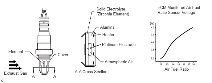
The air fuel ratio sensor generates voltage* that corresponds to the actual air fuel ratio. This sensor voltage is used to provide the ECM with feedback so that it can control the air fuel ratio. The ECM determines the deviation from the stoichiometric air fuel ratio level, and regulates the fuel injection duration. If the air fuel ratio sensor malfunctions, the ECM is unable to control the air fuel ratio accurately.
The air fuel ratio sensor is a planar type and integrated with the heater, which heats the solid electrolyte (zirconia element). This heater is controlled by the ECM. When the intake air volume is low (the exhaust gas temperature is low), a current flows into the heater to heat the sensor, in order to facilitate accurate oxygen concentration detection. In addition, the sensor and heater portions are a narrow type. The heat generated by the heater is conducted to the solid electrolyte through the alumina, therefore sensor activation is accelerated.
In order to obtain a high purification rate of the carbon monoxide (CO), hydrocarbon (HC) and nitrogen oxide (NOx) components in the exhaust gas, a three-way catalytic converter is used. For the most efficient use of the three-way catalytic converter, the air fuel ratio must be precisely controlled so that it is always close to the stoichiometric level.
*: Value changes inside the ECM. Since the air fuel ratio sensor is a current output element, the current is converted into a voltage inside the ECM. Any measurements taken at the air fuel ratio sensor or ECM connectors will show a constant voltage.
| DTC No. | Detection Item | DTC Detection Condition | Trouble Area | MIL | Memory | Note |
|---|---|---|---|---|---|---|
| P219519 | A/F (O2) Sensor Signal Biased/Stuck Lean Bank 1 Sensor 1 Circuit Current Above Threshold | While the fuel-cut operation is performed (during vehicle deceleration), the air fuel ratio sensor current is 2.2 mA or higher for 3 seconds or more (2 trip detection logic). | ·
Open or short in air fuel ratio sensor (Bank 1 sensor 1) circuit ·
Air fuel ratio sensor (Bank 1 sensor 1) ·
Intake system ·
Gas leak from exhaust system ·
Fuel pressure (for low pressure side) ·
Fuel pressure (for high pressure side) ·
Fuel injector assembly (for port injection) ·
Fuel injector assembly (for direct injection) ·
Fuel system ·
ECM |
Comes on | DTC stored | SAE Code: P2195 |
| P219524 | A/F (O2) Sensor Signal Biased/Stuck Lean Bank 1 Sensor 1 Signal Stuck High | Both of the following conditions are met for 5 seconds or more (2 trip detection logic):
1.
Air fuel ratio sensor voltage is higher than 3.8 V. 2.
Heated oxygen sensor voltage is 0.21 V or higher. |
·
Open or short in air fuel ratio sensor (Bank 1 sensor 1) circuit ·
Air fuel ratio sensor (Bank 1 sensor 1) ·
Intake system ·
Gas leak from exhaust system ·
Fuel pressure (for low pressure side) ·
Fuel pressure (for high pressure side) ·
Fuel injector assembly (for port injection) ·
Fuel injector assembly (for direct injection) ·
Fuel system ·
ECM |
Comes on | DTC stored | SAE Code: P2195 |
| P219618 | A/F (O2) Sensor Signal Biased/Stuck Rich Bank 1 Sensor 1 Circuit Current Below Threshold | While the fuel-cut operation is performed (during vehicle deceleration), the air fuel ratio sensor current is less than 0.47 mA for 3 seconds or more (2 trip detection logic). | ·
Open or short in air fuel ratio sensor (Bank 1 sensor 1) circuit ·
Air fuel ratio sensor (Bank 1 sensor 1) ·
Intake system ·
Gas leak from exhaust system ·
Fuel pressure (for low pressure side) ·
Fuel pressure (for high pressure side) ·
Fuel injector assembly (for port injection) ·
Fuel injector assembly (for direct injection) ·
Fuel system ·
ECM |
Comes on | DTC stored | SAE Code: P2196 |
| P219623 | A/F (O2) Sensor Signal Biased/Stuck Rich Bank 1 Sensor 1 Signal Stuck Low | Both of the following conditions are met for 5 seconds or more (2 trip detection logic):
1.
Air fuel ratio sensor voltage is less than 2.8 V. 2.
Heated oxygen sensor voltage is less than 0.7 V. |
·
Open or short in air fuel ratio sensor (Bank 1 sensor 1) circuit ·
Air fuel ratio sensor (Bank 1 sensor 1) ·
Intake system ·
Gas leak from exhaust system ·
Fuel pressure (for low pressure side) ·
Fuel pressure (for high pressure side) ·
Fuel injector assembly (for port injection) ·
Fuel injector assembly (for direct injection) ·
Fuel system ·
ECM |
Comes on | DTC stored | SAE Code: P2196 |
| P219719 | A/F (O2) Sensor Signal Biased/Stuck Lean Bank 2 Sensor 1 Circuit Current Above Threshold | While the fuel-cut operation is performed (during vehicle deceleration), the air fuel ratio sensor current is 2.2 mA or higher for 3 seconds or more (2 trip detection logic). | ·
Open or short in air fuel ratio sensor (Bank 2 sensor 1) circuit ·
Air fuel ratio sensor (Bank 2 sensor 1) ·
Intake system ·
Gas leak from exhaust system ·
Fuel pressure (for low pressure side) ·
Fuel pressure (for high pressure side) ·
Fuel injector assembly (for port injection) ·
Fuel injector assembly (for direct injection) ·
Fuel system ·
ECM |
Comes on | DTC stored | SAE Code: P2197 |
| P219724 | A/F (O2) Sensor Signal Biased/Stuck Lean Bank 2 Sensor 1 Signal Stuck High | Both of the following conditions are met for 5 seconds or more (2 trip detection logic):
1.
Air fuel ratio sensor voltage is higher than 3.8 V. 2.
Heated oxygen sensor voltage is 0.21 V or higher. |
·
Open or short in air fuel ratio sensor (Bank 2 sensor 1) circuit ·
Air fuel ratio sensor (Bank 2 sensor 1) ·
Intake system ·
Gas leak from exhaust system ·
Fuel pressure (for low pressure side) ·
Fuel pressure (for high pressure side) ·
Fuel injector assembly (for port injection) ·
Fuel injector assembly (for direct injection) ·
Fuel system ·
ECM |
Comes on | DTC stored | SAE Code: P2197 |
| P219818 | A/F (O2) Sensor Signal Biased/Stuck Rich Bank 2 Sensor 1 Circuit Current Below Threshold | While the fuel-cut operation is performed (during vehicle deceleration), the air fuel ratio sensor current is less than 0.47 mA for 3 seconds or more (2 trip detection logic). | ·
Open or short in air fuel ratio sensor (Bank 2 sensor 1) circuit ·
Air fuel ratio sensor (Bank 2 sensor 1) ·
Intake system ·
Gas leak from exhaust system ·
Fuel pressure (for low pressure side) ·
Fuel pressure (for high pressure side) ·
Fuel injector assembly (for port injection) ·
Fuel injector assembly (for direct injection) ·
Fuel system ·
ECM |
Comes on | DTC stored | SAE Code: P2198 |
| P219823 | A/F (O2) Sensor Signal Biased/Stuck Rich Bank 2 Sensor 1 Signal Stuck Low | Both of the following conditions are met for 5 seconds or more (2 trip detection logic):
1.
Air fuel ratio sensor voltage is less than 2.8 V. 2.
Heated oxygen sensor voltage is less than 0.7 V. |
·
Open or short in air fuel ratio sensor (Bank 2 sensor 1) circuit ·
Air fuel ratio sensor (Bank 2 sensor 1) ·
Intake system ·
Gas leak from exhaust system ·
Fuel pressure (for low pressure side) ·
Fuel pressure (for high pressure side) ·
Fuel injector assembly (for port injection) ·
Fuel injector assembly (for direct injection) ·
Fuel system ·
ECM |
Comes on | DTC stored | SAE Code: P2198 |
- HINT:
- ·
DTCs P219519, P219524, P219618 and P219623 indicate malfunctions related to the bank 1 air fuel ratio sensor circuit.
·DTCs P219719, P219724, P219818 and P219823 indicate malfunctions related to the bank 2 air fuel ratio sensor circuit.
·When any of these DTCs are stored, check the air fuel ratio sensor voltage output by entering the following menus on the GTS: Powertrain / Engine / Data List / A/F (O2) Sensor Voltage B1S1 or A/F (O2) Sensor Voltage B2S1.
·Short-term fuel trim values can also be read using the GTS.
·The ECM regulates the voltages at the A1A+, A2A+, A1A- and A2A- terminals of the ECM to a constant level. Therefore, the air fuel ratio sensor output voltage cannot be confirmed without using the GTS.
·If an air fuel ratio sensor malfunction is detected, the ECM will store a DTC.
MONITOR DESCRIPTION
- Sensor Voltage Detection Monitor:
-
Under air fuel ratio feedback control, If the air fuel ratio sensor output voltage is less than 2.8 V (very rich condition) for 5 seconds despite the heated oxygen sensor output voltage being less than 0.7 V, the ECM stores DTC P219623 or P219823. Alternatively, if the air fuel ratio sensor output voltage is higher than 3.8 V (very lean condition) for 5 seconds despite the heated oxygen sensor output voltage being 0.21 V or higher, DTC P219524 or P219724 is stored.
- Sensor Current Detection Monitor:
-
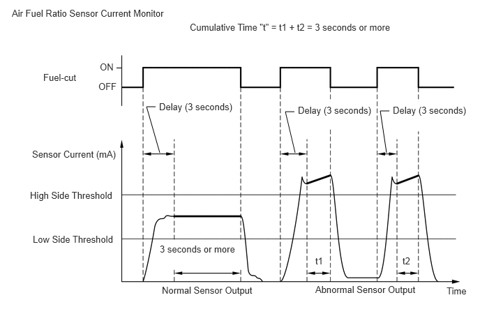
A rich air fuel mixture causes a low air fuel ratio sensor current, and a lean air fuel mixture causes a high air fuel ratio sensor current. Therefore, the sensor output becomes low during acceleration, and it becomes high during deceleration with the throttle valve fully closed. The ECM monitors the air fuel ratio sensor current during fuel-cut and detects any abnormal current values.
-
If the air fuel ratio sensor output is 2.2 mA or higher for 3 seconds or more of cumulative time, the ECM interprets this as a malfunction in the air fuel ratio sensor and stores DTC P219519 or 219719 (stuck on high side). If the air fuel ratio sensor output is less than 0.47 mA for 3 seconds or more of cumulative time, the ECM stores DTC P219618 or P219818 (stuck on low side).
MONITOR STRATEGY
| Required Sensors/Components (Main) | Air fuel ratio sensor |
| Required Sensors/Components (Related) | Heated oxygen sensor |
| Frequency of Operation | Continuous: Sensor voltage detection monitor
Once per driving cycle: Sensor current detection monitor |
| Duration | 3 seconds: Sensor current detection monitor
5 seconds: Sensor voltage detection monitor |
TYPICAL ENABLING CONDITIONS
| Time after engine start | 30 seconds or more |
| Battery voltage | 11 V or higher |
| Air fuel ratio sensor status | Activated |
| Fuel system status | Closed-loop |
| Battery voltage | 11 V or higher |
| Engine coolant temperature | 75°C (167°F) or higher |
| Atmospheric pressure | 76 kPa(abs) [11 psi(abs)] or higher |
| Air fuel ratio sensor status | Activated |
| Continuous time of fuel-cut | 3 seconds or more, and less than 10 seconds |
TYPICAL MALFUNCTION THRESHOLDS
| Heated oxygen sensor voltage | 0.21 V or higher |
| Air fuel ratio sensor voltage | Higher than 3.8 V |
| Heated oxygen sensor voltage | Less than 0.7 V |
| Air fuel ratio sensor voltage | Less than 2.8 V |
| Duration of following condition | 3 seconds or more |
| Air fuel ratio sensor current | 2.2 mA or higher |
| Duration of following condition | 3 seconds or more |
| Air fuel ratio sensor current | Less than 0.47 mA |
CONFIRMATION DRIVING PATTERN
Connect the GTS to the DLC3.
Turn the ignition switch to ON.
Turn the GTS on.
Clear the DTCs (even if no DTCs are stored, perform the clear DTC procedure).
Turn the ignition switch off and wait for at least 30 seconds.
Turn the ignition switch to ON.
Turn the GTS on.
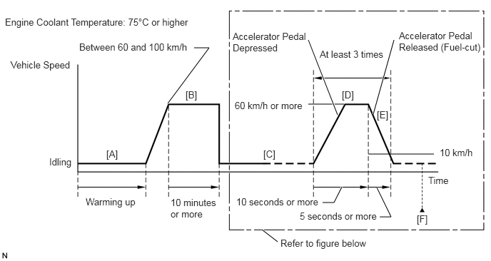
Start the engine and warm it up until the engine coolant temperature reaches 75°C (167°F) or higher [A].
Drive the vehicle at a speed between 60 and 100 km/h (37 and 62 mph) for at least 10 minutes [B].
- CAUTION:
-
When performing the confirmation driving pattern, obey all speed limits and traffic laws.
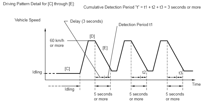
With the shift lever in S or 2nd gear [C], accelerate the vehicle to 60 km/h (37 mph) or more by depressing the accelerator pedal for at least 10 seconds [D].
- CAUTION:
-
When performing the confirmation driving pattern, obey all speed limits and traffic laws.
Soon after performing step [D] above, release the accelerator pedal for at least 5 seconds without depressing the brake pedal in order to execute fuel-cut control [E].
Allow the vehicle to decelerate until the vehicle speed decreases to less than 10 km/h (6 mph).
Repeat steps [C] through [E] above at least 3 times in one driving cycle.
Enter the following menus: Powertrain / Engine / Trouble Codes [F].
Read the pending DTCs.
- HINT:
- ·
If a pending DTC is output, the system is malfunctioning.
·If a pending DTC is not output, perform the following procedure.
Enter the following menus: Powertrain / Engine / Utility / All Readiness.
Input the DTC: P219519, P219524, P219618, P219623, P219719, P219724, P219818 or P219823.
Check the DTC judgment result.
| GTS Display | Description |
|---|---|
| NORMAL | ·
DTC judgment completed ·
System normal |
| ABNORMAL | ·
DTC judgment completed ·
System abnormal |
| INCOMPLETE | ·
DTC judgment not completed ·
Perform driving pattern after confirming DTC enabling conditions |
- HINT:
- ·
If the judgment result is NORMAL, the system is normal.
·If the judgment result is ABNORMAL, the system has a malfunction.
·If the judgment result is INCOMPLETE, perform steps [B] through [F] again.
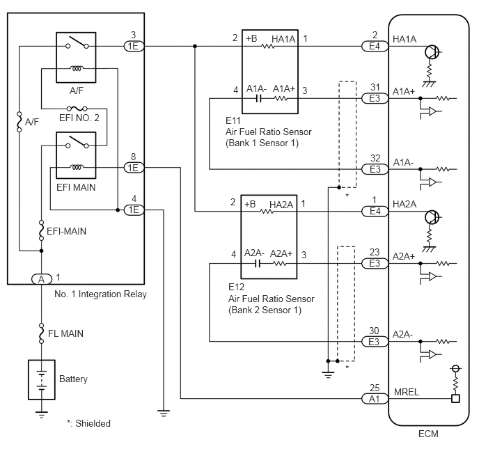
WIRING DIAGRAM
CAUTION / NOTICE / HINT
- NOTICE:
-
Inspect the fuses for circuits related to this system before performing the following procedure.
- HINT:
- ·
A low air fuel ratio sensor voltage could be caused by a rich air fuel mixture. Check for conditions that would cause the engine to run rich.
·A high air fuel ratio sensor voltage could be caused by a lean air fuel mixture. Check for conditions that would cause the engine to run lean.
·Bank 1 refers to the bank that includes the No. 1 cylinder*.
*: The No. 1 cylinder is the cylinder which is farthest from the transmission.
·Bank 2 refers to the bank that does not include the No. 1 cylinder.
·Sensor 1 refers to the sensor closest to the engine assembly.
·Sensor 2 refers to the sensor farthest away from the engine assembly.
·Read Freeze Frame Data using the GTS. The ECM records vehicle and driving condition information as Freeze Frame Data the moment a DTC is stored. When troubleshooting, Freeze Frame Data can help determine if the vehicle was moving or stationary, if the engine was warmed up or not, if the air fuel ratio was lean or rich, and other data from the time the malfunction occurred.
PROCEDURE
Connect the GTS to the DLC3.
Turn the ignition switch to ON.
Turn the GTS on.
Enter the following menus: Powertrain / Engine / Trouble Codes.
Read the DTCs.
- Powertrain > Engine > Trouble Codes
- 50001 372
- Result:
Result Proceed to DTC P219519, P219524, P219618, P219623, P219719, P219724, P219818 or P219823 is output A DTC P219519, P219524, P219618, P219623, P219719, P219724, P219818 or P219823 and P013613, P013617, P01361C, P015613, P015617 or P01561C are output DTC P219519, P219524, P219618, P219623, P219719, P219724, P219818 or P219823 and other DTCs are output B
- HINT:
-
If any DTCs relating to the air fuel ratio sensor (DTCs for the air fuel ratio sensor heater or air fuel ratio sensor admittance) are output, troubleshoot those DTCs first.
A
B
Has the vehicle run out of fuel in the past?
- Result:
Proceed to YES NO
YES
NO
Connect the GTS to the DLC3.
Turn the ignition switch to ON.
Turn the GTS on.
Clear the DTC.
- Powertrain > Engine > Clear DTCs
- 50002 372
Turn the ignition switch off and wait for at least 30 seconds.
- Result:
Proceed to NEXT
NEXT
Drive the vehicle in accordance with the driving pattern described in Confirmation Driving Pattern.
Enter the following menus: Powertrain / Engine / Utility / All Readiness.
- Powertrain > Engine > Utility
-
Tester Display All Readiness - 50005 372 20
Input the DTC: P219519, P219524, P219618, P219623, P219719, P219724, P219818 or P219823.
Check the DTC judgment result.
- Result:
Result Proceed to NORMAL
(DTCs are not output)A ABNORMAL
(DTC P219519, P219524, P219618, P219623, P219719, P219724, P219818 or P219823 is output)B
A
B
Connect the GTS to the DLC3.
Turn the ignition switch to ON.
Turn the GTS on.
Clear the DTC.
- Powertrain > Engine > Clear DTCs
- 50002 372
Turn the ignition switch off and wait for at least 30 seconds.
- Result:
Proceed to NEXT
NEXT
Enter the following menus: Powertrain / Engine / Data List / A/F (O2) Sensor Current B1S1 or A/F (O2) Sensor Current B2S1.
- Powertrain > Engine > Data List
-
Tester Display A/F (O2) Sensor Current B1S1 A/F (O2) Sensor Current B2S1 - 50003 372 230,432
Check the test value of the air fuel ratio sensor output current during fuel-cut, referring to the Driving Pattern Detail for [C] through [E] in Confirmation Driving Pattern.
- HINT:
- ·
To measure the air fuel ratio sensor current precisely, perform the fuel-cut operation as long as possible.
·If it is difficult to measure the air fuel ratio sensor current, use the snapshot function of the GTS.
- Result:
Test Value Proceed to Within normal range
(0.47 mA or higher, and less than 2.2 mA)A Outside normal range
(Less than 0.47 mA, or 2.2 mA or higher)B
A
B
Connect the GTS to the DLC3.
Turn the ignition switch to ON.
Turn the GTS on.
Start the engine and warm it up until the engine coolant temperature reaches 75°C (167°F) or higher.
Warm up the air fuel ratio sensor at an engine speed of 2500 rpm for 90 seconds.
Enter the following menus: Powertrain / Engine / Active Test / Control the Injection Volume for A/F Sensor / Data List / Coolant Temperature, A/F (O2) Sensor Voltage B1S1 and O2 Sensor Voltage B1S2 or A/F (O2) Sensor Voltage B2S1 and O2 Sensor Voltage B2S2.
- Powertrain > Engine > Active Test
-
Active Test Display Control the Injection Volume for A/F Sensor -
Data List Display Coolant Temperature A/F (O2) Sensor Voltage B1S1 A/F (O2) Sensor Voltage B2S1 O2 Sensor Voltage B1S2 O2 Sensor Voltage B2S2 - 50004 372 8 205,225,512,218,510
Perform the Control the Injection Volume for A/F Sensor operation with the engine idling.
Monitor the output voltages of the air fuel ratio and heated oxygen sensors (A/F (O2) Sensor Voltage B1S1 and O2 Sensor Voltage B1S2 or A/F (O2) Sensor Voltage B2S1 and O2 Sensor Voltage B2S2) displayed on the GTS.
- HINT:
- ·
The Control the Injection Volume for A/F Sensor operation lowers the fuel injection volume by 12.5% or increases the injection volume by 12.5%.
·The air fuel ratio sensor has an output delay of a few seconds and the heated oxygen sensor has a maximum output delay of approximately 20 seconds.
·If the sensor output voltage does not change (almost no reaction) while performing the Active Test, the sensor may be malfunctioning.
- Standard:
GTS Display (Sensor) Injection Volume Status Voltage A/F (O2) Sensor Voltage B1S1
A/F (O2) Sensor Voltage B2S1
(Air fuel ratio)12.5% Rich Below 3.1 V -12.5% Lean Higher than 3.4 V O2 Sensor Voltage B1S2
O2 Sensor Voltage B2S2
(Heated oxygen)12.5% Rich Higher than 0.55 V -12.5% Lean Below 0.4 V
- Result:
Status of A/F (O2) Sensor Voltage B1S1 or A/F (O2) Sensor Voltage B2S1 Status of O2 Sensor Voltage B1S2 or O2 Sensor Voltage B2S2 Air Fuel Ratio Condition and Air Fuel Ratio Sensor Condition Proceed to Lean Lean Actual air fuel ratio lean A Rich Rich Actual air fuel ratio rich Lean Lean/Rich Air fuel ratio sensor malfunction B Rich Lean/Rich Air fuel ratio sensor malfunction Lean/Rich Lean/Rich Normal
Lean: During the Control the Injection Volume for A/F Sensor of the Active Test, the air fuel ratio sensor output voltages (A/F (O2) Sensor Voltage B1S1 and A/F (O2) Sensor Voltage B2S1) are consistently higher than 3.4 V, and the heated oxygen sensor output voltages (O2 Sensor Voltage B1S2 and O2 Sensor Voltage B2S2) are consistently below 0.4 V.
Rich: During the Control the Injection Volume for A/F Sensor of the Active Test, the A/F (O2) Sensor Voltage B1S1 and A/F (O2) Sensor Voltage B2S1 are consistently below 3.1 V, and the O2 Sensor Voltage B1S2 and O2 Sensor Voltage B2S2 are consistently higher than 0.55 V.
Lean/Rich: During Control the Injection Volume for A/F Sensor of the Active Test, the output voltage of the air fuel ratio sensor or heated oxygen sensor alternates correctly.
- HINT:
-
Refer to "Data List / Active Test" [A/F (O2) Sensor Voltage B1S1, A/F (O2) Sensor Voltage B2S1, O2 Sensor Voltage B1S2 and O2 Sensor Voltage B2S2].
A
B
Check the intake system for vacuum leaks.
- OK:
No leaks from the intake system.
- HINT:
-
Perform "Inspection After Repair" after repairing or replacing the intake system.
- Result:
Proceed to OK NG
OK
NG
Check for exhaust gas leaks.
- OK:
No gas leaks in exhaust system.
- HINT:
-
Perform "Inspection After Repair" after repairing or replacing the exhaust system.
- Result:
Proceed to OK NG
OK
NG
Check the fuel pressure (for low pressure side).
- Result:
Proceed to OK NG
OK
NG
Inspect the fuel injector assembly (for port injection) (whether fuel volume is high or low, and whether injection pattern is poor).
- HINT:
-
Perform "Inspection After Repair" after replacing the fuel injector assembly (for port injection).
- Result:
Proceed to OK NG
OK
NG
Connect the GTS to the DLC3.
Start the engine.
Turn the GTS on.
Enter the following menus: Powertrain / Engine / Data List / Engine Speed, Coolant Temperature, Fuel Pressure (High) and Injection Mode.
- Powertrain > Engine > Data List
-
Tester Display Engine Speed Coolant Temperature Fuel Pressure (High) Injection Mode - 50003 372 211,205,265,294
Start the engine and warm it up until the engine coolant temperature is 75°C (167°F) or higher with all the accessories switched off.
According to the display on the GTS, read the Data List.
- Standard:
GTS Display Condition Specified Condition Fuel Pressure (High) ·Shift position: P or neutral
·A/C: Off
·Engine warmed up
·Engine Speed: 3000 rpm
·Injection Mode: Direct
2400 to 20000 kPag
- Result:
Proceed to OK NG
OK
NG
Inspect the fuel injector assembly (for direct injection).
- HINT:
-
Perform "Inspection After Repair" after replacing the fuel injector assembly (for direct injection).
- Result:
Proceed to OK NG
OK
NG
Replace the air fuel ratio sensor.
- HINT:
-
Perform "Inspection After Repair" after replacing the air fuel ratio sensor.
- Result:
Proceed to NEXT
NEXT
Connect the GTS to the DLC3.
Turn the ignition switch to ON.
Turn the GTS on.
Clear the DTC.
- Powertrain > Engine > Clear DTCs
- 50002 372
Turn the ignition switch off and wait for at least 30 seconds.
- Result:
Proceed to NEXT
NEXT
Drive the vehicle in accordance with the driving pattern described in Confirmation Driving Pattern.
Enter the following menus: Powertrain / Engine / Utility / All Readiness.
- Powertrain > Engine > Utility
-
Tester Display All Readiness - 50005 372 20
Input the DTC: P219519, P219524, P219618, P219623, P219719, P219724, P219818 or P219823.
Check the DTC judgment result.
- Result:
Result Proceed to NORMAL
(DTCs are not output)A ABNORMAL
(DTC P219519, P219524, P219618, P219623, P219719, P219724, P219818 or P219823 is output)B
A
B
Check the fuel lines for leaks or blockage.
- Result:
Proceed to OK NG
OK
NG
Replace the air fuel ratio sensor.
- HINT:
-
Perform "Inspection After Repair" after replacing the air fuel ratio sensor.
- Result:
Proceed to NEXT
NEXT
Connect the GTS to the DLC3.
Turn the ignition switch to ON.
Turn the GTS on.
Clear the DTC.
- Powertrain > Engine > Clear DTCs
- 50002 372
Turn the ignition switch off and wait for at least 30 seconds.
- Result:
Proceed to NEXT
NEXT
Drive the vehicle in accordance with the driving pattern described in Confirmation Driving Pattern.
Enter the following menus: Powertrain / Engine / Utility / All Readiness.
- Powertrain > Engine > Utility
-
Tester Display All Readiness - 50005 372 20
Input the DTC: P219519, P219524, P219618, P219623, P219719, P219724, P219818 or P219823.
Check the DTC judgment result.
- Result:
Result Proceed to NORMAL
(DTCs are not output)A ABNORMAL
(DTC P219519, P219524, P219618, P219623, P219719, P219724, P219818 or P219823 is output)B
A
B