7GR-FKS ENGINE CONTROL SFI SYSTEM Fuel Pump Control Circuit
DESCRIPTION
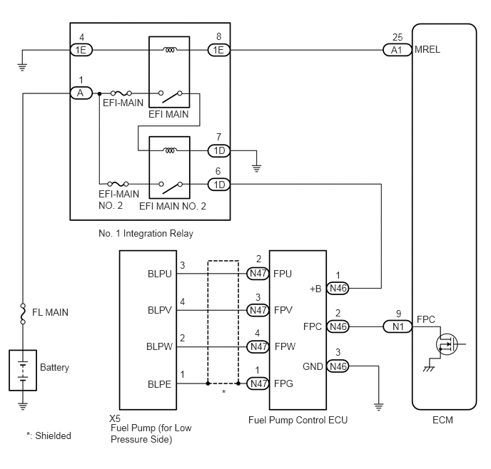
The fuel pump (for low pressure side) circuit consists of the ECM, fuel pump (for low pressure side) and fuel pump control ECU (which operates the fuel pump (for low pressure side)). Based on the engine output, the ECM determines the fuel pump speed. The speed is then converted to a duty signal and sent to the fuel pump control ECU. Based on the signal sent from the ECM, the fuel pump control ECU adjusts the fuel pump (for low pressure side) operation speed.
WIRING DIAGRAM
CAUTION / NOTICE / HINT
- NOTICE:
-
Inspect the fuses for circuits related to this system before performing the following procedure.
PROCEDURE
| *1 | Fuel Pump Control ECU | - | - |
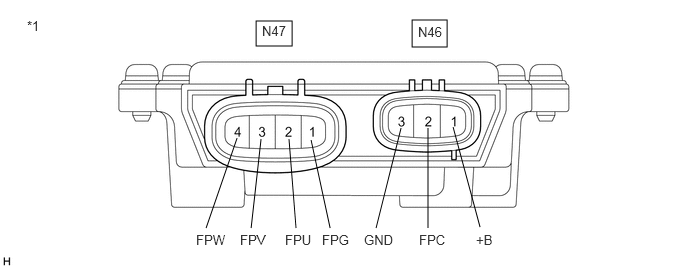
Measure the resistance according to the value(s) in the table below.
- Standard Resistance:
Tester Connection Condition Specified Condition N46-1 (+B) - N46-3 (GND) Always 200 Ω or higher N46-1 (+B) - N46-2 (FPC) Always 2 kΩ or higher N46-2 (FPC) - N46-3 (GND) Always 10 kΩ or higher N47-1 (FPG) - N46-3 (GND) Always 1 kΩ or higher N47-2 (FPU) - N46-3 (GND) Always 2 kΩ or higher N47-3 (FPV) - N46-3 (GND) Always 2 kΩ or higher N47-4 (FPW) - N46-3 (GND) Always 2 kΩ or higher
- HINT:
-
This procedure checks for an internal short of the fuel pump control ECU when its transistor is stuck on.
- Result:
Proceed to OK NG
OK
NG
| *a | Front view of wire harness connector
(to Fuel Pump Control ECU) |
Disconnect the fuel pump control ECU connector.
Turn the ignition switch to ON.
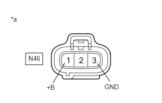
Measure the voltage according to the value(s) in the table below.
- Standard Voltage:
Tester Connection Condition Specified Condition N46-1 (+B) - N46-3 (GND) Ignition switch ON 11 to 14 V
- HINT:
-
Make a note of the measured voltage as it may be used in a following Active Test.
- Result:
Proceed to OK NG
OK
NG
Disconnect the fuel pump control ECU connector.
Disconnect the ECM connector.
Measure the resistance according to the value(s) in the table below.
- Standard Resistance:
Tester Connection Condition Specified Condition N46-2 (FPC) - N1-9 (FPC) Always Below 1 Ω N46-2 (FPC) or N1-9 (FPC) - Body ground and other terminals Always 10 kΩ or higher
- Result:
Proceed to OK NG
OK
NG
| *1 | Fuel Pump Control ECU | - | - |
Disconnect the N47 fuel pump control ECU connector.
Connect the GTS to the DLC3.
Turn the ignition switch to ON.
Turn the GTS on.
Enter the following menus: Powertrain / Engine / Active Test / Fuel Pump Single Phase Energization.
- Powertrain > Engine > Active Test
-
Tester Display Fuel Pump Single Phase Energization - 50004 372 49
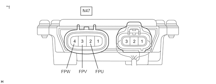
Operate the fuel pump control ECU using the Active Test function and measure the voltage according to the value(s) in the table below.
- Standard Voltage:
Tester Connection GTS Operation Specified Condition N47-2 (FPU) - Body ground U Phase 4.4 to 8.4 V* N47-3 (FPV) - Body ground V Phase 4.4 to 8.4 V* N47-4 (FPW) - Body ground W Phase 4.4 to 8.4 V*
- HINT:
- ·
*: This Active Test restricts the fuel pump control ECU assembly output duty cycle to 50%. Therefore, the output voltage of the fuel pump control ECU assembly will be approximately 50% of the power source voltage measured in a previous step.
·Before performing this inspection, check that the battery voltage is between 11 and 14 V (not depleted).
- Result:
Result Proceed to The U phase, V phase and W phase are all normal A The U phase, V phase or W phase is abnormal B The U phase, V phase and W phase are all abnormal C
A
B
C
Disconnect the fuel pump control ECU connector.
Disconnect the fuel pump (for low pressure side) connector.
Measure the resistance according to the value(s) in the table below.
- Standard Resistance:
Tester Connection Condition Specified Condition N47-2 (FPU) - X5-3 (BLPU) Always Below 1 Ω N47-3 (FPV) - X5-4 (BLPV) Always Below 1 Ω N47-4 (FPW) - X5-2 (BLPW) Always Below 1 Ω N47-2 (FPU) or X5-3 (BLPU) - Body ground and other terminals Always 10 kΩ or higher N47-3 (FPV) or X5-4 (BLPV) - Body ground and other terminals Always 10 kΩ or higher N47-4 (FPW) or X5-2 (BLPW) - Body ground and other terminals Always 10 kΩ or higher
- Result:
Proceed to OK NG
- HINT:
-
Perform "Inspection After Repair" after replacing the fuel pump (for low pressure side).
OK
NG
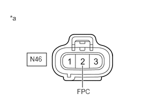
| *a | Front view of wire harness connector
(to Fuel Pump Control ECU) |
Disconnect the fuel pump control ECU connector.
Connect the GTS to the DLC3.
Turn the ignition switch to ON.
Turn the GTS on.
Enter the following menus: Powertrain / Engine / Active Test / Fuel Pump Single Phase Energization.
- Powertrain > Engine > Active Test
-
Tester Display Fuel Pump Single Phase Energization - 50004 372 49
Operate the fuel pump control ECU using the Active Test function and measure the resistance according to the value(s) in the table below.
- Standard Resistance:
Tester Connection GTS Operation Specified Condition N46-2 (FPC) - Body ground Before Active Test → During Active Test Before Active Test: Resistance is stable → During Active Test: Resistance fluctuates*
- HINT:
-
*: Using the Active Test, duty control of the transistors in the ECM will be performed. Due to the duty control, resistance of the FPC terminal will be unstable during the Active Test. If the resistance is stable before the Active Test and fluctuates while performing the Active Test, it can be determined that the transistor is operating. If the transistor does not operate during the Active Test, the ECM may be malfunctioning.
- Result:
Proceed to OK NG
OK
NG
Disconnect the fuel pump control ECU connector.
Measure the resistance according to the value(s) in the table below.
- Standard Resistance:
Tester Connection Condition Specified Condition N46-3 (GND) - Body ground Always Below 1 Ω
- Result:
Proceed to OK NG
OK
NG
- Result:
Proceed to OK NG
OK
NG
Remove the No. 1 integration relay from the No. 1 engine room relay block and junction block assembly.
Disconnect the fuel pump control ECU connector.
Measure the resistance according to the value(s) in the table below.
- Standard Resistance:
Tester Connection Condition Specified Condition 1D-6 - N46-1 (+B) Always Below 1 Ω 1D-6 or N46-1 (+B) - Body ground and other terminals Always 10 kΩ or higher
- Result:
Proceed to OK NG
OK
NG