RM35X0E _51 Engine / Hybrid System _078720 7GR-FKS ENGINE CONTROL _0381907 SFI SYSTEM J

7GR-FKS ENGINE CONTROL  SFI SYSTEM  VC Output Circuit  


DESCRIPTION

The ECM constantly generates a 5 V power source voltage from the battery voltage supplied to the +B, +B2 (BATT) terminals to operate the microprocessor. The ECM also provides this power to the sensors through the VC output circuit.
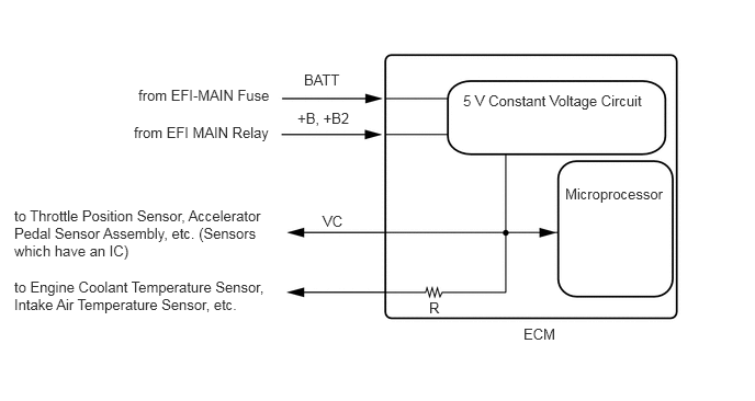
A256646E91
1.313,0.823 3.125,1.125 1.813,0.302 10 false from EFI-MAIN Fuse 1.271,1.177 3.031,1.531 1.76,0.354 10 false from EFI MAIN Relay 0.135,1.969 2.625,2.469 2.49,0.5 10 false to Throttle Position Sensor, Accelerator Pedal Sensor Assembly, etc. (Sensors which have an IC) 0.135,2.646 2.563,3.031 2.427,0.385 10 false to Engine Coolant Temperature Sensor, Intake Air Temperature Sensor, etc. 4.969,3.094 5.313,3.406 0.344,0.313 10 false ECM 2.885,0.677 3.563,1 0.677,0.323 10 false BATT 2.823,1.042 3.49,1.292 0.667,0.25 10 false +B, +B2 3.063,2.021 3.427,2.25 0.365,0.229 10 false VC 4.396,0.875 6.188,1.229 1.792,0.354 10 false 5 V Constant Voltage Circuit 5.365,1.76 6.354,2.115 0.99,0.354 10 false Microprocessor 4.073,2.844 4.333,3.063 0.26,0.219 10 false R

When the VC circuit has a short circuit, the microprocessor in the ECM and sensors that are supplied power through the VC circuit are deactivated because power is not supplied from the VC circuit. When the system is in this condition, it will not start.

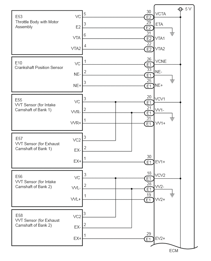
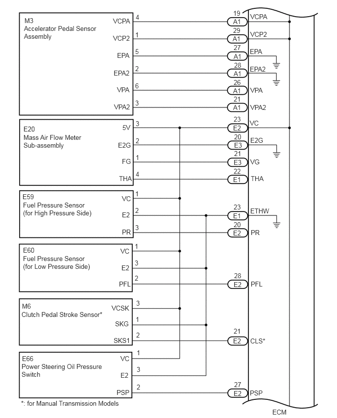
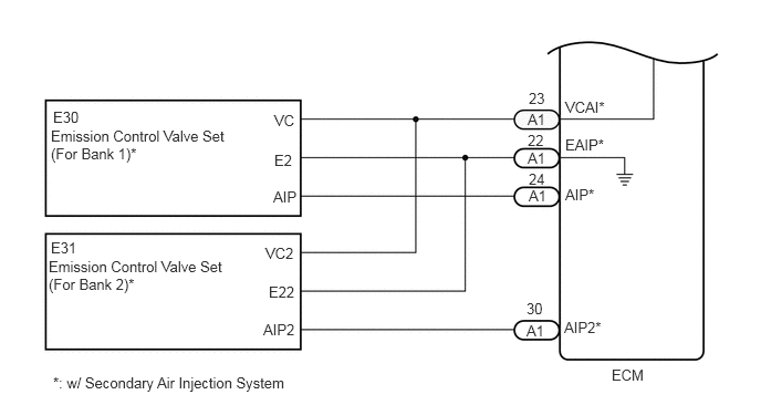
WIRING DIAGRAM

·

VC Output Circuit

A358794E17
0.521,0.479 0.979,0.677 0.458,0.198 10 false E53 0.51,2.052 0.969,2.25 0.458,0.198 10 false E10 0.51,3.313 0.969,3.51 0.458,0.198 10 false E55 0.531,4.625 0.99,4.823 0.458,0.198 10 false E57 0.521,5.917 0.979,6.115 0.458,0.198 10 false E56 0.531,7.24 0.99,7.438 0.458,0.198 10 false E58 2.844,0.385 3.302,0.583 0.458,0.198 10 false 5 2.844,1.104 3.302,1.302 0.458,0.198 10 false 6 2.854,1.469 3.313,1.667 0.458,0.198 10 false 4 2.844,0.729 3.302,0.927 0.458,0.198 10 false 3 2.854,2 3.313,2.198 0.458,0.198 10 false 1 2.854,2.354 3.313,2.552 0.458,0.198 10 false 2 2.844,2.719 3.302,2.917 0.458,0.198 10 false 3 2.844,3.271 3.302,3.469 0.458,0.198 10 false 3 2.844,4.583 3.302,4.781 0.458,0.198 10 false 3 2.844,3.635 3.302,3.833 0.458,0.198 10 false 2 2.854,4.938 3.313,5.135 0.458,0.198 10 false 2 2.854,6.219 3.313,6.417 0.458,0.198 10 false 2 2.854,5.854 3.313,6.052 0.458,0.198 10 false 3 2.844,4 3.302,4.198 0.458,0.198 10 false 1 2.844,5.302 3.302,5.5 0.458,0.198 10 false 1 2.854,6.573 3.313,6.771 0.458,0.198 10 false 1 2.844,7.917 3.302,8.115 0.458,0.198 10 false 1 2.844,7.552 3.302,7.75 0.458,0.198 10 false 2 2.833,7.177 3.292,7.375 0.458,0.198 10 false 3 0.521,0.656 2.021,1.448 1.5,0.792 10 false Throttle Body with Motor Assembly 0.5,2.208 2.354,2.531 1.854,0.323 10 false Crankshaft Position Sensor 0.51,3.479 1.917,4.208 1.406,0.729 10 false VVT Sensor (for Intake Camshaft of Bank 1) 0.521,4.802 2.063,5.531 1.542,0.729 10 false VVT Sensor (for Exhaust Camshaft of Bank 1) 0.521,6.094 1.927,6.823 1.406,0.729 10 false VVT Sensor (for Intake Camshaft of Bank 2) 0.521,7.406 2.063,8.135 1.542,0.729 10 false VVT Sensor (for Exhaust Camshaft of Bank 2) 2.563,0.479 3.021,0.677 0.458,0.198 10 false VC 2.573,0.833 3.031,1.031 0.458,0.198 10 false E2 2.479,1.198 2.938,1.396 0.458,0.198 10 false VTA 2.417,1.563 2.875,1.76 0.458,0.198 10 false VTA2 2.542,2.083 3,2.281 0.458,0.198 10 false VC 2.51,2.438 2.969,2.635 0.458,0.198 10 false NE- 2.531,3.375 2.99,3.573 0.458,0.198 10 false VC 2.417,3.719 2.875,3.917 0.458,0.198 10 false VVR- 2.396,4.094 2.854,4.292 0.458,0.198 10 false VVR+ 2.479,4.677 2.938,4.875 0.458,0.198 10 false VC2 2.521,5.021 2.979,5.219 0.458,0.198 10 false EX- 2.5,5.396 2.958,5.594 0.458,0.198 10 false EX+ 2.531,5.958 2.99,6.156 0.458,0.198 10 false VC 2.438,6.302 2.896,6.5 0.458,0.198 10 false VVL- 2.406,6.688 2.865,6.885 0.458,0.198 10 false VVL+ 2.49,7.281 2.948,7.479 0.458,0.198 10 false VC2 2.521,7.635 2.979,7.833 0.458,0.198 10 false EX- 2.49,2.823 2.948,3.021 0.458,0.198 10 false NE+ 2.5,8.021 2.958,8.219 0.458,0.198 10 false EX+ 5.271,8.021 5.729,8.219 0.458,0.198 10 false EV2+ 5.75,8.438 6.208,8.635 0.458,0.198 10 false ECM 5.271,6.698 5.729,6.896 0.458,0.198 10 false VV2+ 5.271,6.26 5.729,6.458 0.458,0.198 10 false VV2- 5.26,5.875 5.719,6.073 0.458,0.198 10 false VCV2 5.271,5.417 5.729,5.615 0.458,0.198 10 false EV1+ 5.281,4.104 5.74,4.302 0.458,0.198 10 false VV1+ 5.271,3.656 5.729,3.854 0.458,0.198 10 false VV1- 5.26,3.281 5.719,3.479 0.458,0.198 10 false VCV1 5.26,2.813 5.719,3.01 0.458,0.198 10 false NE+ 5.271,2.354 5.729,2.552 0.458,0.198 10 false NE- 5.281,2 5.74,2.198 0.458,0.198 10 false VCNE 5.271,1.219 5.729,1.417 0.458,0.198 10 false VTA1 6.292,0.219 6.75,0.417 0.458,0.198 10 false 5 V 5.281,0.385 5.74,0.583 0.458,0.198 10 false VCTA 5.271,1.573 5.729,1.771 0.458,0.198 10 false VTA2 4.979,0.313 5.281,0.51 0.302,0.198 10 false 30 4.979,0.677 5.281,0.875 0.302,0.198 10 false 29 4.979,1.042 5.281,1.24 0.302,0.198 10 false 31 4.99,1.406 5.292,1.604 0.302,0.198 10 false 22 4.99,1.927 5.302,2.167 0.313,0.24 10 false 26 4.99,2.281 5.302,2.521 0.313,0.24 10 false 33 4.99,2.656 5.302,2.896 0.313,0.24 10 false 25 4.99,3.208 5.302,3.448 0.313,0.24 10 false 20 4.99,3.583 5.302,3.823 0.313,0.24 10 false 21 4.979,3.938 5.292,4.177 0.313,0.24 10 false 31 4.99,5.24 5.302,5.479 0.313,0.24 10 false 30 4.99,5.802 5.302,6.042 0.313,0.24 10 false 18 4.99,6.167 5.302,6.406 0.313,0.24 10 false 28 4.979,6.542 5.292,6.781 0.313,0.24 10 false 19 4.979,7.865 5.292,8.104 0.313,0.24 10 false 29 4.958,8.052 5.271,8.292 0.313,0.24 10 false E1 4.958,6.719 5.271,6.958 0.313,0.24 10 false E1 4.979,6.354 5.292,6.594 0.313,0.24 10 false E1 4.969,5.99 5.281,6.229 0.313,0.24 10 false E1 4.979,5.438 5.292,5.677 0.313,0.24 10 false E1 4.969,4.125 5.281,4.365 0.313,0.24 10 false E1 4.979,3.76 5.292,4 0.313,0.24 10 false E1 4.979,3.406 5.292,3.646 0.313,0.24 10 false E1 4.979,2.844 5.292,3.083 0.313,0.24 10 false E1 4.979,2.479 5.292,2.719 0.313,0.24 10 false E1 4.979,2.115 5.292,2.354 0.313,0.24 10 false E1 4.979,1.594 5.292,1.833 0.313,0.24 10 false E2 4.979,1.229 5.292,1.469 0.313,0.24 10 false E2 4.958,0.865 5.271,1.104 0.313,0.24 10 false E2 4.969,0.5 5.281,0.74 0.313,0.24 10 false E2 5.281,0.74 5.74,0.938 0.458,0.198 10 false ETA

A439406E03
5.323,0.271 5.938,0.469 0.615,0.198 10 false VCPA 5.323,0.646 5.938,0.844 0.615,0.198 10 false VCP2 5.313,1.01 5.927,1.208 0.615,0.198 10 false EPA 5.313,1.385 5.927,1.583 0.615,0.198 10 false EPA2 5.323,1.833 5.938,2.031 0.615,0.198 10 false VPA 5.323,2.198 5.938,2.396 0.615,0.198 10 false VPA2 5.313,2.531 5.927,2.729 0.615,0.198 10 false VC 5.323,2.896 5.938,3.094 0.615,0.198 10 false E2G 5.323,3.354 5.938,3.552 0.615,0.198 10 false VG 5.333,3.708 5.948,3.906 0.615,0.198 10 false THA 5.333,5.948 5.792,6.146 0.458,0.198 10 false PFL 5.323,4.396 5.938,4.594 0.615,0.198 10 false ETHW 5.333,4.854 5.646,5.052 0.313,0.198 10 false PR 5.323,7.156 5.781,7.354 0.458,0.198 10 false CLS* 5.313,8.26 5.771,8.458 0.458,0.198 10 false PSP 4.958,0.198 5.271,0.396 0.313,0.198 10 false 19 4.958,0.563 5.271,0.76 0.313,0.198 10 false 29 4.969,0.927 5.281,1.125 0.313,0.198 10 false 27 4.979,5.771 5.292,5.969 0.313,0.198 10 false 28 4.969,1.667 5.281,1.865 0.313,0.198 10 false 26 4.969,2.021 5.281,2.219 0.313,0.198 10 false 21 4.969,2.448 5.281,2.646 0.313,0.198 10 false 23 4.979,2.823 5.292,3.021 0.313,0.198 10 false 20 4.969,3.552 5.281,3.75 0.313,0.198 10 false 22 4.979,3.177 5.292,3.375 0.313,0.198 10 false 21 4.969,4.313 5.281,4.51 0.313,0.198 10 false 23 4.969,4.688 5.281,4.885 0.313,0.198 10 false 20 4.979,1.302 5.292,1.5 0.313,0.198 10 false 28 4.979,8.083 5.292,8.281 0.313,0.198 10 false 27 0.51,0.521 2.313,1.469 1.802,0.948 10 false Accelerator Pedal Sensor Assembly 0.5,2.833 1.979,3.885 1.479,1.052 10 false Mass Air Flow Meter Sub-assembly 0.49,4.271 1.948,4.833 1.458,0.563 10 false Fuel Pressure Sensor (for High Pressure Side) 0.49,5.406 1.948,5.896 1.458,0.49 10 false Fuel Pressure Sensor (for Low Pressure Side) 0.458,7.698 2.313,8.25 1.854,0.552 10 false Power Steering Oil Pressure Switch 0.458,6.594 2.49,7.104 2.031,0.51 10 false Clutch Pedal Stroke Sensor* 2.406,0.365 3.021,0.563 0.615,0.198 10 false VCPA 2.406,0.729 3.021,0.927 0.615,0.198 10 false VCP2 2.49,1.094 3.104,1.292 0.615,0.198 10 false EPA 2.417,1.469 3.031,1.667 0.615,0.198 10 false EPA2 2.49,1.823 3.104,2.021 0.615,0.198 10 false VPA 2.427,2.188 3.042,2.385 0.615,0.198 10 false VPA2 2.604,2.625 2.917,2.823 0.313,0.198 10 false 5V 2.51,3 3.125,3.198 0.615,0.198 10 false E2G 2.594,3.344 2.906,3.542 0.313,0.198 10 false FG 2.531,3.708 3.146,3.906 0.615,0.198 10 false THA 2.594,4.135 3.208,4.333 0.615,0.198 10 false VC 2.594,4.479 3.208,4.677 0.615,0.198 10 false E2 2.594,4.844 2.906,5.042 0.313,0.198 10 false PR 2.531,5.948 2.99,6.146 0.458,0.198 10 false PFL 2.563,5.25 3.177,5.448 0.615,0.198 10 false VC 2.583,5.604 3.198,5.802 0.615,0.198 10 false E2 2.417,7.146 2.875,7.344 0.458,0.198 10 false SKS1 2.448,6.792 3.063,6.99 0.615,0.198 10 false SKG 2.375,6.458 2.99,6.656 0.615,0.198 10 false VCSK 2.563,7.531 3.177,7.729 0.615,0.198 10 false VC 2.563,7.885 3.177,8.083 0.615,0.198 10 false E2 2.479,8.25 2.938,8.448 0.458,0.198 10 false PSP 2.885,0.281 3.042,0.479 0.156,0.198 10 false 4 2.875,0.656 3.031,0.854 0.156,0.198 10 false 1 2.875,1.01 3.031,1.208 0.156,0.198 10 false 5 2.875,1.375 3.031,1.573 0.156,0.198 10 false 2 2.875,1.74 3.031,1.938 0.156,0.198 10 false 6 2.875,2.104 3.031,2.302 0.156,0.198 10 false 3 2.885,2.542 3.042,2.74 0.156,0.198 10 false 3 2.885,2.906 3.042,3.104 0.156,0.198 10 false 2 2.885,3.26 3.042,3.458 0.156,0.198 10 false 1 2.885,3.615 3.042,3.813 0.156,0.198 10 false 4 2.875,4.031 3.031,4.229 0.156,0.198 10 false 1 2.875,4.385 3.031,4.583 0.156,0.198 10 false 2 2.875,4.75 3.031,4.948 0.156,0.198 10 false 3 2.865,5.146 3.021,5.344 0.156,0.198 10 false 1 2.865,5.5 3.021,5.698 0.156,0.198 10 false 3 2.865,5.823 3.021,6.021 0.156,0.198 10 false 2 5.792,8.667 6.25,8.865 0.458,0.198 10 false ECM 0.521,0.354 0.833,0.552 0.313,0.198 10 false M3 4.958,0.375 5.271,0.573 0.313,0.198 10 false A1 4.948,0.74 5.26,0.938 0.313,0.198 10 false A1 4.969,1.479 5.281,1.677 0.313,0.198 10 false A1 4.958,1.844 5.271,2.042 0.313,0.198 10 false A1 4.958,2.198 5.271,2.396 0.313,0.198 10 false A1 4.969,1.115 5.281,1.313 0.313,0.198 10 false A1 0.5,2.656 0.813,2.854 0.313,0.198 10 false E20 4.958,2.635 5.271,2.833 0.313,0.198 10 false E2 4.969,3.365 5.281,3.563 0.313,0.198 10 false E3 4.979,3 5.292,3.198 0.313,0.198 10 false E3 4.958,3.729 5.271,3.927 0.313,0.198 10 false E1 0.479,4.094 0.792,4.292 0.313,0.198 10 false E59 4.958,4.5 5.271,4.698 0.313,0.198 10 false E1 4.958,4.865 5.271,5.063 0.313,0.198 10 false E2 0.49,5.229 0.802,5.427 0.313,0.198 10 false E60 4.969,5.958 5.281,6.156 0.313,0.198 10 false E2 0.469,6.417 0.781,6.615 0.313,0.198 10 false M6 2.896,6.354 3.052,6.552 0.156,0.198 10 false 3 2.896,7.031 3.052,7.229 0.156,0.198 10 false 2 2.885,6.698 3.042,6.896 0.156,0.198 10 false 1 4.969,6.948 5.281,7.146 0.313,0.198 10 false 21 4.958,7.156 5.271,7.354 0.313,0.198 10 false E2 4.969,8.271 5.281,8.469 0.313,0.198 10 false E2 2.906,7.406 3.063,7.604 0.156,0.198 10 false 1 2.906,8.135 3.063,8.333 0.156,0.198 10 false 2 2.906,7.76 3.063,7.958 0.156,0.198 10 false 3 0.469,7.531 0.927,7.729 0.458,0.198 10 false E66 0.448,8.479 2.635,8.74 2.188,0.26 10 false *: for Manual Transmission Models

A439407E04
5.76,3.448 6.219,3.646 0.458,0.198 10 false ECM 5.323,0.927 5.938,1.125 0.615,0.198 10 false VCAI* 5.323,1.281 5.938,1.479 0.615,0.198 10 false EAIP* 5.323,1.75 5.938,1.948 0.615,0.198 10 false AIP* 5.313,3 5.927,3.198 0.615,0.198 10 false AIP2* 0.479,1.198 2.177,1.656 1.698,0.458 10 false Emission Control Valve Set (For Bank 1)* 0.458,2.427 2.146,2.833 1.688,0.406 10 false Emission Control Valve Set (For Bank 2)* 2.573,1.771 3.188,1.969 0.615,0.198 10 false AIP 2.583,1.427 3.198,1.625 0.615,0.198 10 false E2 2.583,1.052 3.198,1.25 0.615,0.198 10 false VC 2.531,2.667 3.146,2.865 0.615,0.198 10 false E22 2.5,2.302 3.115,2.5 0.615,0.198 10 false VC2 2.479,3.021 3.094,3.219 0.615,0.198 10 false AIP2 0.5,3.521 2.927,3.729 2.427,0.208 10 false *: w/ Secondary Air Injection System 4.969,1.042 5.26,1.229 0.292,0.188 10 false A1 4.969,1.406 5.26,1.594 0.292,0.188 10 false A1 4.979,1.76 5.271,1.948 0.292,0.188 10 false A1 4.958,3.031 5.25,3.219 0.292,0.188 10 false A1 4.979,0.844 5.271,1.031 0.292,0.188 10 false 23 4.969,1.24 5.26,1.427 0.292,0.188 10 false 22 0.5,1.021 0.792,1.208 0.292,0.188 10 false E30 0.479,2.25 0.771,2.438 0.292,0.188 10 false E31 4.979,1.604 5.271,1.792 0.292,0.188 10 false 24 4.958,2.823 5.25,3.01 0.292,0.188 10 false 30


CAUTION / NOTICE / HINT

NOTICE:

Check the fuses for circuits related to this system before performing the following inspection procedure.


PROCEDURE

1.CHECK CONNECTION BETWEEN GTS AND ECM
a.

Connect the GTS to the DLC3.


b.

Turn the ignition switch to ON.


c.

Turn the GTS on.


d.

Check the communication between the GTS and ECM.

HINT:

It can be checked using the "Engine" item of the Data List.


Result:
Result Proceed to
Communication is not possible A
Communication is possible B


A

2.CHECK TERMINAL VOLTAGE (POWER SOURCE OF ECM)

B

2.CHECK TERMINAL VOLTAGE (POWER SOURCE OF ECM)
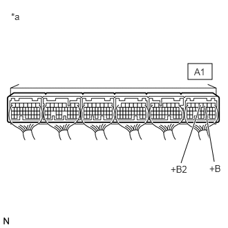
A216119C28
2.833,0.958 3.198,1.198 0.365,0.24 3.083,1.594 3.229,2.438 true 3.021,1.583 2.729,2.458 true 0.167,0.167 0.417,0.333 0.25,0.167 10 false *a 2.927,1 3.24,1.281 0.313,0.281 10 false A1 3.156,2.458 3.406,2.708 0.25,0.25 10 false +B 2.573,2.469 3.083,2.698 0.51,0.229 10 false +B2
*a Component with harness connected
(to ECM)


a.

Turn the ignition switch to ON.


b.

Measure the voltage according to the value(s) in the table below.

Standard Voltage:
Tester Connection Condition Specified Condition
A1-3 (+B) - Body ground Ignition switch ON 11 to 14 V
A1-4 (+B2) - Body ground Ignition switch ON 11 to 14 V


HINT:

If the result is not as specified, since current is not flowing to the +B and +B2 terminals of the ECM, the system may not be started.


Result:
Proceed to
OK
NG


OK

3.CHECK CONNECTION BETWEEN GTS AND ECM (THROTTLE POSITION SENSOR)

NG

3.CHECK CONNECTION BETWEEN GTS AND ECM (THROTTLE POSITION SENSOR)
a.

Disconnect the throttle body with motor assembly connector.


b.

Turn the ignition switch to ON.


c.

Turn the GTS on.


d.

Check the communication between the GTS and ECM.

HINT:

It can be checked using the "Engine" item of the Data List.


Result:
Result Proceed to
Communication is not possible A
Communication is possible B


HINT:

Perform "Inspection After Repair" after replacing the throttle body with motor assembly.

Click hereEngine / Hybrid System>7GR-FKS (ENGINE CONTROL)>SFI SYSTEM>INITIALIZATION


A

4.CHECK CONNECTION BETWEEN GTS AND ECM (ACCELERATOR PEDAL POSITION SENSOR)

B

4.CHECK CONNECTION BETWEEN GTS AND ECM (ACCELERATOR PEDAL POSITION SENSOR)
a.

Disconnect the accelerator pedal sensor assembly connector.


b.

Turn the ignition switch to ON.


c.

Turn the GTS on.


d.

Check the communication between the GTS and ECM.

HINT:

It can be checked using the "Engine" item of the Data List.


Result:
Result Proceed to
Communication is not possible A
Communication is possible B


A

5.CHECK CONNECTION BETWEEN GTS AND ECM (CRANKSHAFT POSITION SENSOR)

B

5.CHECK CONNECTION BETWEEN GTS AND ECM (CRANKSHAFT POSITION SENSOR)
a.

Disconnect the crankshaft position sensor connector.


b.

Turn the ignition switch to ON.


c.

Turn the GTS on.


d.

Check the communication between the GTS and ECM.

HINT:

It can be checked using the "Engine" item of the Data List.


Result:
Result Proceed to
Communication is not possible A
Communication is possible B


A

6.CHECK CONNECTION BETWEEN GTS AND ECM (VVT SENSOR (FOR INTAKE CAMSHAFT OF BANK 1))

B

6.CHECK CONNECTION BETWEEN GTS AND ECM (VVT SENSOR (FOR INTAKE CAMSHAFT OF BANK 1))
a.

Disconnect the VVT sensor (for intake camshaft of bank 1) connector.


b.

Turn the ignition switch to ON.


c.

Turn the GTS on.


d.

Check the communication between the GTS and ECM.

HINT:

It can be checked using the "Engine" item of the Data List.


Result:
Result Proceed to
Communication is not possible A
Communication is possible B


A

7.CHECK CONNECTION BETWEEN GTS AND ECM (VVT SENSOR (FOR INTAKE CAMSHAFT OF BANK 2))

B

7.CHECK CONNECTION BETWEEN GTS AND ECM (VVT SENSOR (FOR INTAKE CAMSHAFT OF BANK 2))
a.

Disconnect the VVT sensor (for intake camshaft of bank 2) connector.


b.

Turn the ignition switch to ON.


c.

Turn the GTS on.


d.

Check the communication between the GTS and ECM.

HINT:

It can be checked using the "Engine" item of the Data List.


Result:
Result Proceed to
Communication is not possible A
Communication is possible B


A

8.CHECK CONNECTION BETWEEN GTS AND ECM (VVT SENSOR (FOR EXHAUST CAMSHAFT OF BANK 1))

B

8.CHECK CONNECTION BETWEEN GTS AND ECM (VVT SENSOR (FOR EXHAUST CAMSHAFT OF BANK 1))
a.

Disconnect the VVT sensor (for exhaust camshaft of bank 1) connector.


b.

Turn the ignition switch to ON.


c.

Turn the GTS on.


d.

Check the communication between the GTS and ECM.

HINT:

It can be checked using the "Engine" item of the Data List.


Result:
Result Proceed to
Communication is not possible A
Communication is possible B


A

9.CHECK CONNECTION BETWEEN GTS AND ECM (VVT SENSOR (FOR EXHAUST CAMSHAFT OF BANK 2))

B

9.CHECK CONNECTION BETWEEN GTS AND ECM (VVT SENSOR (FOR EXHAUST CAMSHAFT OF BANK 2))
a.

Disconnect the VVT sensor (for exhaust camshaft of bank 2) connector.


b.

Turn the ignition switch to ON.


c.

Turn the GTS on.


d.

Check the communication between the GTS and ECM.

HINT:

It can be checked using the "Engine" item of the Data List.


Result:
Result Proceed to
Communication is not possible A
Communication is possible B


A

10.CHECK CONNECTION BETWEEN GTS AND ECM (FUEL PRESSURE SENSOR (FOR HIGH PRESSURE SIDE))

B

10.CHECK CONNECTION BETWEEN GTS AND ECM (FUEL PRESSURE SENSOR (FOR HIGH PRESSURE SIDE))
a.

Disconnect the fuel pressure sensor (for high pressure side) connector.


b.

Turn the ignition switch to ON.


c.

Turn the GTS on.


d.

Check the communication between the GTS and ECM.

HINT:

It can be checked using the "Engine" item of the Data List.


Result:
Result Proceed to
Communication is not possible A
Communication is possible B


HINT:

Perform "Inspection After Repair" after replacing the fuel pressure sensor (for high pressure side).

Click hereEngine / Hybrid System>7GR-FKS (ENGINE CONTROL)>SFI SYSTEM>INITIALIZATION


A

11.CHECK CONNECTION BETWEEN GTS AND ECM (FUEL PRESSURE SENSOR (FOR LOW PRESSURE SIDE))

B

11.CHECK CONNECTION BETWEEN GTS AND ECM (FUEL PRESSURE SENSOR (FOR LOW PRESSURE SIDE))
a.

Disconnect the fuel pressure sensor (for low pressure side) connector.


b.

Turn the ignition switch to ON.


c.

Turn the GTS on.


d.

Check the communication between the GTS and ECM.

HINT:

It can be checked using the "Engine" item of the Data List.


Result:
Result Proceed to
Communication is not possible A
Communication is possible B


HINT:

Perform "Inspection After Repair" after replacing the fuel pressure sensor (for low pressure side).

Click hereEngine / Hybrid System>7GR-FKS (ENGINE CONTROL)>SFI SYSTEM>INITIALIZATION


A

12.CHECK CONNECTION BETWEEN GTS AND ECM (MASS AIR FLOW METER SUB-ASSEMBLY)

B

12.CHECK CONNECTION BETWEEN GTS AND ECM (MASS AIR FLOW METER SUB-ASSEMBLY)
a.

Disconnect the mass air flow meter sub-assembly connector.


b.

Turn the ignition switch to ON.


c.

Turn the GTS on.


d.

Check the communication between the GTS and ECM.

HINT:

It can be checked using the "Engine" item of the Data List.


Result:
Result Proceed to
Communication is not possible (w/ Secondary Air Injection System) A
Communication is not possible (w/o Secondary Air Injection System) B
Communication is possible C


HINT:

Perform "Inspection After Repair" after replacing the mass air flow meter sub-assembly.

Click hereEngine / Hybrid System>7GR-FKS (ENGINE CONTROL)>SFI SYSTEM>INITIALIZATION


A

13.CHECK CONNECTION BETWEEN GTS AND ECM (EMISSION CONTROL VALVE SET (FOR BANK 1))

B

15.CHECK CONNECTION BETWEEN GTS AND ECM (POWER STEERING OIL PRESSURE SWITCH)

C

13.CHECK CONNECTION BETWEEN GTS AND ECM (EMISSION CONTROL VALVE SET (FOR BANK 1))
a.

Disconnect the emission control valve set (for bank 1) connector.


b.

Turn the ignition switch to ON.


c.

Turn the GTS on.


d.

Check the communication between the GTS and ECM.

HINT:

It can be checked using the "Engine" item of the Data List.


Result:
Result Proceed to
Communication is not possible A
Communication is possible B


A

14.CHECK CONNECTION BETWEEN GTS AND ECM (EMISSION CONTROL VALVE SET (FOR BANK 2))

B

14.CHECK CONNECTION BETWEEN GTS AND ECM (EMISSION CONTROL VALVE SET (FOR BANK 2))
a.

Disconnect the emission control valve set (for bank 2) connector.


b.

Turn the ignition switch to ON.


c.

Turn the GTS on.


d.

Check the communication between the GTS and ECM.

HINT:

It can be checked using the "Engine" item of the Data List.


Result:
Result Proceed to
Communication is not possible A
Communication is possible B


A

15.CHECK CONNECTION BETWEEN GTS AND ECM (POWER STEERING OIL PRESSURE SWITCH)

B

15.CHECK CONNECTION BETWEEN GTS AND ECM (POWER STEERING OIL PRESSURE SWITCH)
a.

Disconnect the power steering oil pressure switch connector.


b.

Turn the ignition switch to ON.


c.

Turn the GTS on.


d.

Check the communication between the GTS and ECM.

HINT:

It can be checked using the "Engine" item of the Data List.


Result:
Result Proceed to
Communication is not possible (for Manual Transmission Models) A
Communication is not possible (for Automatic Transmission Models) B
Communication is possible C


A

16.CHECK CONNECTION BETWEEN GTS AND ECM (CLUTCH STROKE SENSOR)

B

17.CHECK HARNESS AND CONNECTOR

C

16.CHECK CONNECTION BETWEEN GTS AND ECM (CLUTCH STROKE SENSOR)
a.

Disconnect the clutch stroke sensor connector.


b.

Turn the ignition switch to ON.


c.

Turn the GTS on.


d.

Check the communication between the GTS and ECM.

HINT:

It can be checked using the "Engine" item of the Data List.


Result:
Result Proceed to
Communication is not possible A
Communication is possible B


A

17.CHECK HARNESS AND CONNECTOR

B

17.CHECK HARNESS AND CONNECTOR
a.

Disconnect the throttle body with motor assembly connector.


b.

Disconnect the accelerator pedal sensor assembly connector.


c.

Disconnect the crankshaft position sensor connector.


d.

Disconnect the VVT sensor (for intake camshaft of bank 1) connector.


e.

Disconnect the VVT sensor (for intake camshaft of bank 2) connector.


f.

Disconnect the VVT sensor (for exhaust camshaft of bank 1) connector.


g.

Disconnect the VVT sensor (for exhaust camshaft of bank 2) connector.


h.

Disconnect the fuel pressure sensor (for high pressure side) connector.


i.

Disconnect the fuel pressure sensor (for low pressure side) connector.


j.

Disconnect the mass air flow meter sub-assembly connector.


k.

Disconnect the power steering oil pressure switch connector.


l.

Disconnect the emission control valve set (for bank 1) connector (w/ Secondary Air Injection System).


m.

Disconnect the emission control valve set (for bank 2) connector (w/ Secondary Air Injection System).


n.

Disconnect the clutch stroke sensor connector (for manual transmission models).


o.

Disconnect the ECM connectors.


p.

Measure the resistance according to the value(s) in the table below.

Standard Resistance:
Tester Connection Condition Specified Condition
E2-30 (VCTA) - Body ground Always 10 kΩ or higher
A1-19 (VCPA) - Body ground Always 10 kΩ or higher
A1-29 (VCP2) - Body ground Always 10 kΩ or higher
E1-26 (VCNE) - Body ground Always 10 kΩ or higher
E1-20 (VCV1) - Body ground Always 10 kΩ or higher
E1-18 (VCV2) - Body ground Always 10 kΩ or higher
E2-23 (VC) - Body ground Always 10 kΩ or higher
A1-23 (VCAI) - Body ground* Always 10 kΩ or higher


*: w/ Secondary Air Injection System


Result:
Proceed to
OK
NG


OK

NG

REPAIR OR REPLACE HARNESS OR CONNECTOR