7GR-FKS ENGINE CONTROL SFI SYSTEM ECM Power Source Circuit
DESCRIPTION
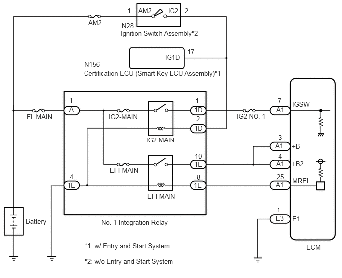
When the ignition switch is turned to ON, the battery voltage is applied to the IGSW terminal of the ECM.
The output signal from the MREL terminal of the ECM causes a current to flow to the coil of the EFI MAIN relay, closing the contacts and supplying power to terminals +B and +B2 of the ECM.
WIRING DIAGRAM
CAUTION / NOTICE / HINT
- NOTICE:
-
Inspect the fuses for circuits related to this system before performing the following inspection procedure.
PROCEDURE
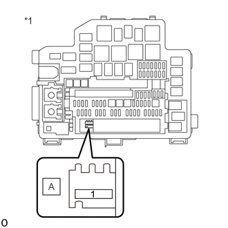
| *1 | No. 1 Engine Room Relay Block and Junction Block Assembly without No. 1 Integration Relay |
Remove the No. 1 integration relay from the No. 1 engine room relay block and junction block assembly.
Measure the voltage according to the value(s) in the table below.
- Standard Voltage:
Tester Connection Condition Specified Condition A-1 - Body ground Always 11 to 14 V
- Result:
Proceed to OK NG
OK
NG
- Result:
Proceed to OK NG
OK
NG
Remove the No. 1 integration relay from the No. 1 engine room relay block and junction block assembly.
Disconnect the ECM connector.
Measure the resistance according to the value(s) in the table below.
- Standard Resistance:
Tester Connection Condition Specified Condition A1-25 (MREL) - 1E-8 Always Below 1 Ω A1-3 (+B) - 1E-10 Always Below 1 Ω A1-4 (+B2) - 1E-10 Always Below 1 Ω A1-25 (MREL) or 1E-8 - Body ground and other terminals Always 10 kΩ or higher A1-3 (+B) or 1E-10 - Body ground and other terminals Always 10 kΩ or higher A1-4 (+B2) or 1E-10 - Body ground and other terminals Always 10 kΩ or higher
- Result:
Proceed to OK NG
OK
NG
Remove the No. 1 integration relay from the No. 1 engine room relay block and junction block assembly.
Measure the resistance according to the value(s) in the table below.
- Standard Resistance:
Tester Connection Condition Specified Condition 1E-4 - Body ground Always Below 1 Ω
- Result:
Proceed to OK NG
OK
NG
Disconnect the ECM connector.
Measure the resistance according to the value(s) in the table below.
- Standard Resistance (Check for Open):
Tester Connection Condition Specified Condition E3-1 (E1) - Body ground Always Below 1 Ω
- Result:
Proceed to OK NG
OK
NG
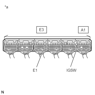
| *a | Component with harness connected
(to ECM) |
Measure the voltage according to the value(s) in the table below.
- Standard Voltage:
Tester Connection Condition Specified Condition A1-7 (IGSW) - E3-1 (E1) Ignition switch ON 11 to 14 V
- Result:
Proceed to OK NG
OK
NG
Remove the No. 1 integration relay from the No. 1 engine room relay block and junction block assembly.
Disconnect the ECM connector.
Measure the resistance according to the value(s) in the table below.
- Standard Resistance:
Tester Connection Condition Specified Condition 1D-1 - A1-7 (IGSW) Always Below 1 Ω 1D-1 or A1-7 (IGSW) - Body ground and other terminals Always 10 kΩ or higher
- Result:
Result Proceed to OK (w/ Entry and Start System) A OK (w/o Entry and Start System) B NG C
A
B
C
Remove the No. 1 integration relay from the No. 1 engine room relay block and junction block assembly.
Disconnect the certification ECU (smart key ECU assembly) connector.
Measure the resistance according to the value(s) in the table below.
- Standard Resistance:
Tester Connection Condition Specified Condition N156-17 (IG1D) - 1D-2 Always Below 1 Ω N156-17 (IG1D) or 1D-2 - Body ground and other terminals Always 10 kΩ or higher
- Result:
Proceed to OK NG
OK
NG
Inspect the ignition switch assembly.
- Result:
Proceed to OK NG
OK
NG
Disconnect the ignition switch assembly connector.
Remove the No. 1 integration relay from the No. 1 engine room relay block and junction block assembly.
Measure the resistance according to the value(s) in the table below.
- Standard Resistance:
Tester Connection Condition Specified Condition N28-2 (IG2) - 1D-2 Always Below 1 Ω N28-2 (IG2) or 1D-2 - Body ground and other terminals Always 10 kΩ or higher
- Result:
Proceed to OK NG
OK
NG