PARKING BRAKE PARKING BRAKE LEVER INSTALLATION
CAUTION / NOTICE / HINT
- HINT:
- ·
Use the same procedure for the RH and LH sides, except where indicated.
·The procedure listed below is for the LHD side.
PROCEDURE

 46201E
1.INSTALL PARKING BRAKE LEVER SUB-ASSEMBLY
46201E
1.INSTALL PARKING BRAKE LEVER SUB-ASSEMBLY
Pass the No. 1 parking brake cable assembly through the parking brake lever sub-assembly.
Temporarily install the adjusting nut to the No. 1 parking brake cable assembly.
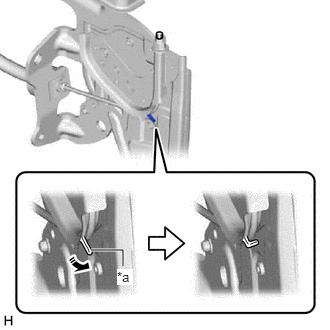
| *a | Claw |

|
Return |
Return the claw to its original position.
- HINT:
-
Move the parking brake lever sub-assembly a few times and check for smooth movement.
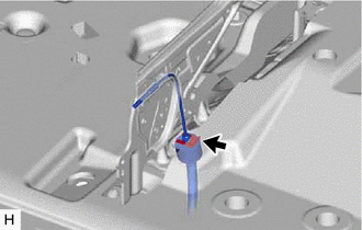
Install the No. 1 parking brake cable assembly to the parking brake lever sub-assembly with a new clip.
- HINT:
-
Install the clip with the floor carpet folded back.
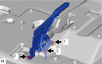
Install the parking brake lever sub-assembly with the 3 bolts.
- Torque:
- 20 N*m (204 kgf*cm, 15 ft.*lbf)
- NOTICE:
-
Tighten the 3 bolts in the order shown in the illustration.
- HINT:
-
Install the parking brake lever sub-assembly with the floor carpet folded back.
for LHD:
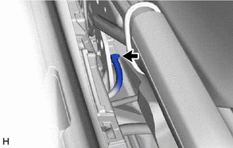
Connect the parking brake switch connector.
for RHD:
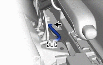
Engage the clamp and connect the parking brake switch connector.
46441
2.TEMPORARILY INSTALL NO. 1 WIRE ADJUSTING NUT
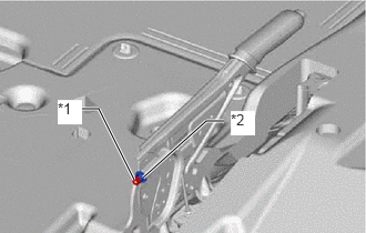
| *1 | Lock Nut |
| *2 | No. 1 Wire Adjusting Nut |
Temporily install the No. 1 wire adjusting nut and lock nut.
58997
3.INSTALL NO. 3 CONSOLE BOX MOUNTING BRACKET (except Separate Seat Type)
4.INSTALL FRONT SEAT ASSEMBLY LH (for Separate Seat Type)
5.INSTALL FRONT SEAT ASSEMBLY LH (Sliding Bench Seat Type)
6.INSTALL FRONT SEAT ASSEMBLY RH (Fixed Bench Seat Type)
58902C
7.INSTALL CONSOLE BOX MOUNTING BRACKET SUB-ASSEMBLY (for Separate Seat Type)
58904B
8.INSTALL PARKING BRAKE HOLE COVER SUB-ASSEMBLY (except Separate Seat Type)
9.ADJUST PARKING BRAKE LEVER TRAVEL
10.INSPECT BRAKE WARNING LIGHT