NAVIGATION / MULTI INFO DISPLAY NAVIGATION SYSTEM Vehicle Speed Signal Circuit between Radio Receiver and Combination Meter
DESCRIPTION
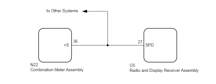
This circuit is necessary for the Automatic Sound Levelizer (ASL) built into the radio and display receiver assembly.
The Automatic Sound Levelizer (ASL) function automatically adjusts the audio system volume in order to compensate for increased vehicle noise (vehicle noise tends to increase as vehicle speed increases). The ASL adjusts the volume based on vehicle speed signals sent from the combination meter assembly.
- HINT:
- ·
A voltage of 12 V or 5 V is output from each ECU and then input to the combination meter assembly. The signal is changed to a pulse signal at the transistor in the combination meter assembly. Each ECU controls its respective system based on this pulse signal.
·If a short occurs in any of the ECUs or in the wire harness connected to an ECU, all systems in the following diagram will not operate normally.
WIRING DIAGRAM
CAUTION / NOTICE / HINT
- NOTICE:
-
When replacing the radio and display receiver assembly, always replace it with a new one. If a radio and display receiver assembly which was installed to another vehicle is used, the following may occur:
- ·
A communication malfunction DTC may be stored.
·The radio and display receiver assembly may not operate normally.
- HINT:
-
Depending on the parts that are replaced during vehicle inspection or maintenance, performing initialization, registration or calibration may be needed. Refer to Precaution for Navigation System.
PROCEDURE

Enter the "Vehicle Signal Check Mode" screen. Refer to Check Vehicle Signal Check Mode in Operation Check.
While driving the vehicle, compare the value displayed for "SPEED" to the reading on the speedometer. Check if these readings are almost equal.
- HINT:
-
The combination meter assembly receives the vehicle speed signal from the skid control ECU via CAN communication. Therefore, perform the following inspection referring to values on the Data List of the skid control ECU because it is the source of the vehicle speed signal.
- OK:
Vehicle speed displayed on the "Vehicle Signal Check Mode" screen is almost the same as the actual vehicle speed measured using the GTS.
- Result:
Proceed to OK NG
OK
NG
| *a | Component with harness connected
(Combination Meter Assembly) |
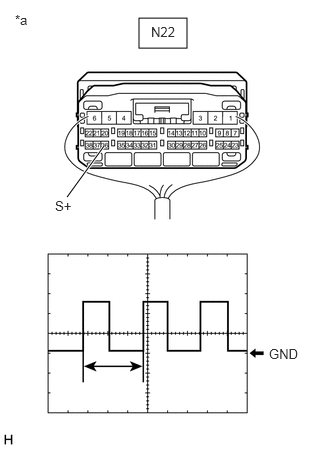
Check the output waveform.
Remove the combination meter assembly with the connector still connected.
Connect an oscilloscope to terminal N22-36 (+S) and body ground.
Turn the ignition switch to ON.
Turn a wheel slowly.
Check the signal waveform according to the condition(s) in the table below.
| Item | Condition |
|---|---|
| Measurement terminal | N22-36 (+S) - Body ground |
| Tool setting | 5 V/DIV., 20 ms./DIV. |
| Vehicle condition | Wheel being rotated |
- OK:
The waveform is similar to that shown in the illustration.
- HINT:
-
When the system is functioning normally, one wheel revolution generates 4 pulses. As the vehicle speed increases, the width indicated by (A) in the illustration narrows.
- Result:
Proceed to OK NG
OK
NG
Disconnect the O5 radio and display receiver assembly connector.
Disconnect the N22 combination meter assembly connector.
Measure the resistance according to the value(s) in the table below.
- Standard Resistance:
Tester Connection Condition Specified Condition O5-27 (SPD) - N22-36 (+S) Always Below 1 Ω
- Result:
Proceed to OK NG
OK
NG