DOOR / HATCH POWER BACK DOOR SYSTEM Power Back Door cannot be Operated Using Kick Sensor
DESCRIPTION
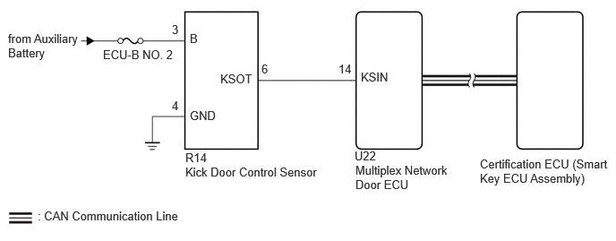
When the kick door control sensor detects a kick operation, it sends an operation signal to the multiplex network door ECU.
WIRING DIAGRAM
CAUTION / NOTICE / HINT
- NOTICE:
- ·
Before troubleshooting, make sure that the "Kick Sensor" customize setting is set to "ON" (The default is "ON").
·The power back door system uses the CAN communication system. Inspect the communication function by following How to Proceed with Troubleshooting. Troubleshoot the power back door system after confirming that the CAN communication system is functioning properly.
for HEV Model: Click herePower Source / Network>NETWORKING>CAN COMMUNICATION SYSTEM (for HEV Model)>HOW TO PROCEED WITH TROUBLESHOOTING202307,999999,_57,_104409,_0606038,RM100000002C0LC,
for Gasoline Model: Click herePower Source / Network>NETWORKING>CAN COMMUNICATION SYSTEM (for Gasoline Model)>HOW TO PROCEED WITH TROUBLESHOOTING202307,202405,_57,_104409,_0605911,RM100000002C07Y,202405,999999,_57,_104409,_0605911,RM100000002NU3H,
·The power back door system uses the LIN communication system. Inspect the communication function by following How to Proceed with Troubleshooting. Troubleshoot the power back door system after confirming that the LIN communication system is functioning properly.
·Check the smart entry and start system (for Entry Function) first before troubleshooting the power back door system.
for HEV Model: Click hereVehicle Interior>THEFT DETERRENT / KEYLESS ENTRY>SMART ENTRY AND START SYSTEM (for Entry Function, HEV Model)>HOW TO PROCEED WITH TROUBLESHOOTING202307,999999,_58,_115230,_0606511,RM100000002C244,
for Gasoline Model: Click hereVehicle Interior>THEFT DETERRENT / KEYLESS ENTRY>SMART ENTRY AND START SYSTEM (for Entry Function, Gasoline Model)>HOW TO PROCEED WITH TROUBLESHOOTING202307,999999,_58,_115230,_0606491,RM100000002C221,
·Before troubleshooting, be sure to read Precautions for Hands Free Power Back Door.
·If the multiplex network door ECU has been removed and installed or replaced, or if any of the connectors have been disconnected, initialize the power back door system.
·After performing work, using the GTS, read the Data List item "Kick Sensor Connection" and check that the kick door control sensor is connected.
·Inspect the fuses for circuits related to this system before performing the following procedure.
PROCEDURE
Check that the power back door function on the multi-information display in the combination meter assembly is set to ON.
- Result:
Result Proceed to Power back door function on the multi-information display in the combination meter assembly is set to ON (power back door system operation is permitted) A Power back door function on the multi-information display in the combination meter assembly is set to OFF (power back door system operation is prohibited) B
A
B
Using the GTS, check that the customization setting "Kick Sensor Operation Function with ACC ON" is set to "Enable" (The default is "Enable").
- Result:
Result Proceed to Using the GTS, the customization setting "Kick Sensor Operation Function with ACC ON" is set to "Enable" (Power back door system operation is permitted) A Using the GTS, the customization setting "Kick Sensor Operation Function with ACC ON" is set to "Disable" (Power back door system operation is prohibited) B
A
B
Check the operations of the power back door system other than the kick sensor function.
- Result:
Result Proceed to Power back door system operates normally A Power back door system does not operate normally B
A
B
Check for DTCs.
- Body Electrical > Back Door > Trouble Codes
- 50001 489
- OK:
DTC is not output.
- Result:
Proceed to OK NG
OK
NG
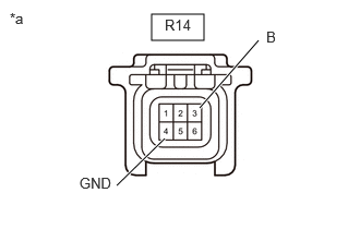
| *a | Front view of wire harness connector
(to Kick Door Control Sensor) |
Disconnect the kick door control sensor connector.
Measure the resistance according to the value(s) in the table below.
- Standard Resistance:
Tester Connection Condition Specified Condition R14-4 (GND) - Body ground Always Below 1 Ω
Measure the voltage according to the value(s) in the table below.
- Standard Voltage:
Tester Connection Switch Condition Specified Condition R14-3 (B) - Body ground Ignition switch off 11 to 14 V
- Result:
Proceed to OK NG
OK
NG
Disconnect the R14 kick door control sensor connector.
Disconnect the U22 multiplex network door ECU connector.
Measure the resistance according to the value(s) in the table below.
- Standard Resistance:
Tester Connection Condition Specified Condition R14-6 (KSOT) - U22-14 (KSIN) Always Below 1 Ω R14-6 (KSOT) or U22-14 (KSIN) - Body ground Always 10 kΩ or higher
- Result:
Proceed to OK NG
OK
NG
Temporarily replace the kick door control sensor with a new or normally functioning one.
Click hereVehicle Exterior>DOOR / HATCH>KICK SENSOR>REMOVAL202307,999999,_59,_113746,_0510849,RM100000002COEA,
- Result:
Proceed to NEXT
NEXT
Check that the power back door system functions normally in response to kick sensor operation.
- Result:
Result Proceed to Power back door system operates normally A Power back door system does not operate normally B
A
B