STOP AND START STOP AND START SYSTEM Starter Signal Circuit
DESCRIPTION
The engine stop and start ECU can activates the ST NO. 1 relay to operation the starter assembly.
WIRING DIAGRAM
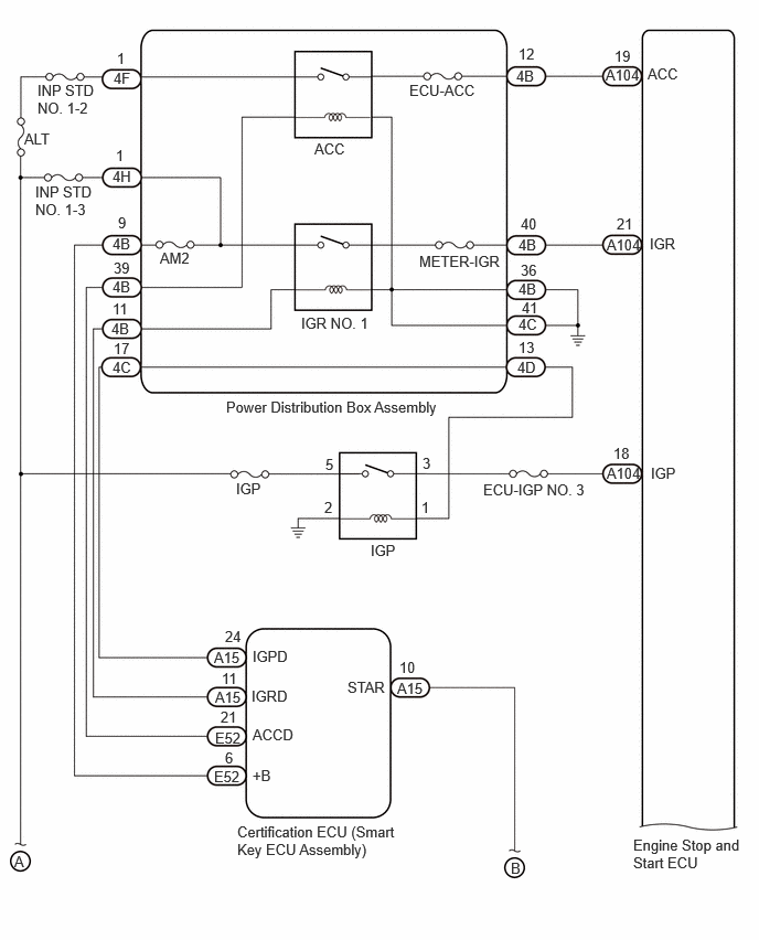
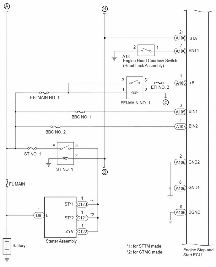
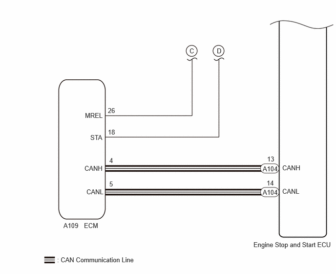
CAUTION / NOTICE / HINT
- NOTICE:
- ·
Before replacing the engine stop and start ECU, read the number of starter operations and write it into a new engine stop and start ECU.
·After replacing the engine stop and start ECU or air conditioning amplifier assembly, reset and perform learning of the air conditioning information in the engine stop and start ECU.
·After replacing the starter assembly, perform initialization of the number of starter operations stored in the engine stop and start ECU.
·After replacing the engine stop and start ECU, perform learning of the external backup boost converter (eco run vehicle converter assembly).
·When the starter assembly is replaced, "ST NO. 1 relay" must be also replaced.
·Inspect the fuses for circuits related to this system before performing the following procedure.
·When disconnecting and reconnecting the battery.
- HINT:
-
When disconnecting and reconnecting the battery, there is an automatic learning function that completes learning when the respective system is used.
PROCEDURE
Turn the ignition switch START and check that the engine cranks.
- Result:
Result Proceed to Engine cranks A Engine does not crank B
A
B
Check whether the engine cranks while the Active Test "Starter" is being performed.
- Powertrain > Stop and Start > Active Test
-
Tester Display Starter(Hood Close) - 50004 392 42017
- HINT:
-
The Active Test "Starter" is stopped automatically 3 seconds after the starter assembly begins operating.
- Standard:
Engine cranks
- Result:
Proceed to OK NG
OK
NG
Check the vehicle control history (RoB).
- Powertrain > Engine > Utility
-
Tester Display Vehicle Control History (RoB) - 50005 372 55
- Result:
Result Proceed to Engine control system Vehicle Control History (RoB) is not output A Engine Difficult to Start is output B Result other than Engine Difficult to Start is output C
- HINT:
- ·
If the value of "Cranking Time" is approximately 1.5 seconds, the stop and start control system or starter system may be malfunctioning.
·If the value of "Cranking Time" is small (approximately 0.5 seconds or less: the minimum value varies depending on the model), the engine control system may be malfunctioning.
·The Data List item "Cranking Time" indicates the length of time starter operation is requested by the engine stop and start ECU. If the engine speed exceeds the specified value, the engine stop and start ECU cancels its start request.
A
B
C
Select Engine Difficult to Start from the Vehicle Control History to display the data from the time of control.
- Powertrain > Engine > Utility
-
Tester Display Vehicle Control History (RoB) - 50005 372 55
Check the output data.
- HINT:
- ·
Checking the Freeze Frame Data allows the vehicle conditions at the time of detection to be confirmed.
·As Vehicle Control History may be overwritten whenever the trigger conditions are met, make sure to save the Vehicle Control History data before performing any inspections.
- Result:
Result Proceed to Engine speed does not rise to approximately 300 rpm (Starter does not rotate) A Engine speed rises to approximately 300 rpm (Starter rotates) B
A
B
Select a vehicle control history item to display the data from the time of control.
- Powertrain > Stop and Start > Utility
-
Tester Display Vehicle Control History (RoB) - 50005 392 55
Check the output data.
- Result:
Tester Display Result Proceed to Engine Stall History during Stop&Start (Hood Open) Yes A Engine Stall History during Stop&Start (Collision or Battery Voltage Low) Yes B Engine Stall History during Engine Starting (Collision) Yes Engine Stall History during Engine Starting (Collision) Yes C Vehicle control history item is not output or No is displayed for the results of all of the Freeze Frame Data above
A
B
C
- NOTICE:
-
Before performing this step, check that the engine hood can be opened by pulling the hood lock control cable.
Enter the following menus: Powertrain / Stop and Start / Data List / Hood Courtesy Switch.
- Powertrain > Stop and Start > Data List
-
Tester Display Hood Courtesy Switch - 50003 392 207
According to the display on the GTS, read the Data List.
- OK:
GTS Display Condition Normal Condition Hood Courtesy Switch Engine hood closed ON Engine hood open OFF
- Result:
Result OK NG
OK
NG
Inspect the engine hood courtesy switch (hood lock assembly).
- Result:
Result OK NG
OK
NG
Disconnect the engine hood courtesy switch (hood lock assembly) connector.
Measure the resistance according to the value(s) in the table below.
- Standard Resistance:
Tester Connection Condition Specified Condition Click Location & Routing(A18)Location & Routingewd_type=routing;type=c;code=A18
Click Connector(A18)Engine Compartment>Engine Room Main Wire / Transmission Wire>Engine Hood Courtesy Switch (Hood Lock Assembly)ewd_type=component;type=c;code=A18;pinno=2
A18-2 - Body ground Always Below 1 Ω
- Result:
Result OK NG
OK
NG
Disconnect the engine stop and start ECU connector.
Disconnect the engine hood courtesy switch (hood lock assembly) connector.
Measure the resistance according to the value(s) in the table below.
- Standard Resistance:
Tester Connection Condition Specified Condition Click Location & Routing(A106,A18)Location & Routingewd_type=routing;type=c,c;code=A106,A18
Click Connector(A106)Instrument Panel>Engine Room Main Wire>Engine Stop and Start ECUewd_type=component;type=c;code=A106;pinno=7
Click Connector(A18)Engine Compartment>Engine Room Main Wire / Transmission Wire>Engine Hood Courtesy Switch (Hood Lock Assembly)ewd_type=component;type=c;code=A18;pinno=1
A106-7 (BNT1) - A18-1 Always Below 1 Ω A106-7 (BNT1) - Body ground Always 10 kΩ or higher A18-1 - Body ground Always 10 kΩ or higher
- Result:
Result OK NG
OK
NG
Check if the vehicle was in a collision when the engine stalled.
- Result:
Result Proceed to Vehicle was in collision when engine stalled A Vehicle was not in collision when engine stalled B
- HINT:
-
When "Engine Stall History during Stop&Start (Collision or Battery Voltage Low)" or "Engine Stall History during Engine Starting (Collision)" is stored:
-
This may have been stored because the vehicle was in a collision or a collision detection signal was input while stop and start control was operating.
A
B
Disconnect the engine stop and start ECU connector.
Remove the ST NO. 1 relay from the No. 1 engine room relay block and No. 1 junction block assembly.
Disconnect the certification ECU (smart key ECU assembly) connector.
Disconnect the ECM connector.
Measure the resistance according to the value(s) in the table below.
- Standard Resistance:
Tester Connection Condition Specified Condition Click Location & Routing(A106)Location & Routingewd_type=routing;type=c;code=A106
Click Connector(A106)Instrument Panel>Engine Room Main Wire>Engine Stop and Start ECUewd_type=component;type=c;code=A106;pinno=21
A106-21 (STA) - ST NO. 1 relay terminal 2 Always Below 1 Ω A106-21 (STA) - Body ground Always 10 kΩ or higher ST NO. 1 relay terminal 2 - Body ground Always 10 kΩ or higher
- Result:
Proceed to OK NG
OK
NG
Remove the ST NO. 1 relay from the No. 1 engine room relay block and No. 1 junction block assembly
Measure the resistance according to the value(s) in the table below.
- Standard Resistance:
Tester Connection Condition Specified Condition ST NO. 1 relay terminal 1 - Body ground Always Below 1 Ω
- Result:
Proceed to OK NG
OK
NG
Remove the ST NO. 1 relay from the No. 1 engine room relay block and No. 1 junction block assembly
Measure the voltage according to the value(s) in the table below.
- Standard Voltage:
Tester Connection Condition Specified Condition ST NO. 1 relay terminal 5 - Body ground Always 9.5 to 14 V
- Result:
Proceed to OK NG
OK
NG
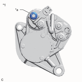
| *1 | Starter Assembly |
| *a | B9-1 (B) |
Measure the voltage according to the value(s) in the table below.
- Standard Voltage:
Tester Connection Condition Specified Condition Click Location & Routing(B9)Location & Routingewd_type=routing;type=c;code=B9
B9-1 (B) - Body ground Always 9.5 to 14 V
- NOTICE:
-
Before performing this step, check that the starter assembly connector B9 is not disconnected or loose.
- Result:
Proceed to OK NG
OK
NG
Remove the ST NO. 1 relay from the No. 1 engine room relay block and No. 1 junction block assembly.
Disconnect the starter assembly connector.
Measure the resistance according to the value(s) in the table below.
- Standard Resistance (for SFTM made):
Tester Connection Condition Specified Condition Click Location & Routing(C123,C122)Location & Routingewd_type=routing;type=c,c;code=C123,C122
Click Connector(C123)Engine Compartment>Engine Wire>Starter Assemblyewd_type=component;type=c;code=C123;pinno=1
Click Connector(C122)Engine Compartment>Engine Wire>Starter Assemblyewd_type=component;type=c;code=C122;pinno=1
ST NO. 1 relay terminal 3 - C123-1 (ST) Always Below 1 Ω ST NO. 1 relay terminal 3 - C122-1 (ZYV) Always Below 1 Ω
- Standard Resistance (for GTMC made):
Tester Connection Condition Specified Condition Click Location & Routing(C122)Location & Routingewd_type=routing;type=c;code=C122
Click Connector(C122)Engine Compartment>Engine Wire>Starter Assemblyewd_type=component;type=c;code=C122;pinno=1
ST NO. 1 relay terminal 3 - C121-1 (ST) Always Below 1 Ω ST NO. 1 relay terminal 3 - C122-1 (ZYV) Always Below 1 Ω
- Result:
Proceed to OK NG
OK
NG
- Result:
Proceed to OK NG
OK
NG
- Result:
Proceed to OK NG
OK
- HINT:
-
If arriving at this item from the item "Drive command is being sent from the engine stop and start ECU but the starter itself is not moving" of "After Engine Stops due to Stop and Start System, Engine does not Restart" in Stop and Start / Stop and Start System / Problem Symptoms Table, go to SIMULATION METHOD.
NG
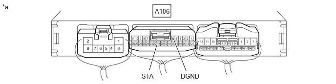
| *a | Component with harness connected
(Engine Stop and Start ECU) |
- | - |
Measure the voltage according to the value(s) in the table below.
- Standard Voltage:
Tester Connection Condition Specified Condition Click Location & Routing(A106)Location & Routingewd_type=routing;type=c;code=A106
Click Connector(A106)Instrument Panel>Engine Room Main Wire>Engine Stop and Start ECUewd_type=component;type=c;code=A106;pinno=21,6
A106-21 (STA) - A106-6 (DGND) Cranking commanded via Active Test item Starter(Hood Close) 6 to 14 V
- HINT:
-
The Active Test "Starter" is stopped automatically 3 seconds after the starter assembly begins operating.
- Result:
Proceed to OK NG
OK
NG
- HINT:
-
If arriving at this item from the item "Drive command is being sent from the engine stop and start ECU but the starter itself is not moving" of "After Engine Stops due to Stop and Start System, Engine does not Restart" in Stop and Start / Stop and Start System / Problem Symptoms Table, go to SIMULATION METHOD.
Check whether the engine cranks while the Active Test "Starter" is being performed.
- Powertrain > Stop and Start > Active Test
-
Tester Display Starter(Hood Close) - 50004 392 42017
- NOTICE:
-
The Active Test "Starter" is stopped automatically 3 seconds after the starter assembly begins operating.
- Standard:
Engine cranks
- Result:
Result Proceed to Engine cranks A Engine does not crank B
A
B
Disconnect the certification ECU (smart key ECU assembly) connector.
Remove the ST NO. 1 relay from the No. 1 engine room relay block and No. 1 junction block assembly.
Disconnect the ECM connector.
Disconnect the engine stop and start ECU connector.
Measure the resistance according to the value(s) in the table below.
- Standard Resistance:
Tester Connection Condition Specified Condition Click Location & Routing(A15)Location & Routingewd_type=routing;type=c;code=A15
Click Connector(A15)Instrument Panel>Engine Room Main Wire>Smart Key ECU Assemblyewd_type=component;type=c;code=A15;pinno=10
A15-10 (STAR) - ST NO. 1 relay terminal 2 Always Below 1 Ω
- Result:
Proceed to OK NG
OK
NG
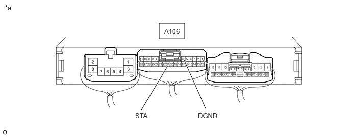
| *a | Component with harness connected
(Engine Stop and Start ECU) |
- | - |
Measure the voltage according to the value(s) in the table below.
- Standard Voltage:
Tester Connection Condition Specified Condition Click Location & Routing(A106)Location & Routingewd_type=routing;type=c;code=A106
Click Connector(A106)Instrument Panel>Engine Room Main Wire>Engine Stop and Start ECUewd_type=component;type=c;code=A106;pinno=21,6
A106-21 (STA) - A106-6 (DGND) Engine start 6 to 14 V
- Result:
Proceed to OK NG
OK
NG
- Result:
Proceed to OK NG
OK
NG
Remove the ST NO. 1 relay from the No. 1 engine room relay block and No. 1 junction block assembly.
Measure the voltage according to the value(s) in the table below.
- Standard Voltage:
Tester Connection Condition Specified Condition ST NO. 1 relay terminal 5 - Body ground Always 9.5 to 14 V
- Result:
Proceed to OK NG
OK
NG
Remove the ST NO. 1 relay from the No. 1 engine room relay block and No. 1 junction block assembly.
Disconnect the starter assembly connector.
Measure the resistance according to the value(s) in the table below.
- Standard Resistance (for SFTM made):
Tester Connection Condition Specified Condition Click Location & Routing(C123,C122)Location & Routingewd_type=routing;type=c,c;code=C123,C122
Click Connector(C123)Engine Compartment>Engine Wire>Starter Assemblyewd_type=component;type=c;code=C123;pinno=1
Click Connector(C122)Engine Compartment>Engine Wire>Starter Assemblyewd_type=component;type=c;code=C122;pinno=1
ST NO. 1 relay terminal 3 - C123-1 (ST) Always Below 1 Ω ST NO. 1 relay terminal 3 - C122-1 (ZYV) Always Below 1 Ω
- Standard Resistance (for GTMC made):
Tester Connection Condition Specified Condition Click Location & Routing(C122)Location & Routingewd_type=routing;type=c;code=C122
Click Connector(C122)Engine Compartment>Engine Wire>Starter Assemblyewd_type=component;type=c;code=C122;pinno=1
ST NO. 1 relay terminal 3 - C121-1 (ST) Always Below 1 Ω ST NO. 1 relay terminal 3 - C122-1 (ZYV) Always Below 1 Ω
- Result:
Proceed to OK NG
OK
NG
Remove the ST NO. 1 relay from the No. 1 engine room relay block and No. 1 junction block assembly
Measure the resistance according to the value(s) in the table below.
- Standard Resistance:
Tester Connection Condition Specified Condition ST NO. 1 relay terminal 1 - Body ground Always Below 1 Ω
- Result:
Proceed to OK NG
OK
NG
Disconnect the engine stop and start ECU connector.
Remove the ST NO. 1 relay from the No. 1 engine room relay block and No. 1 junction block assembly.
Disconnect the certification ECU (smart key ECU assembly) connector.
Disconnect the ECM connector.
Measure the resistance according to the value(s) in the table below.
- Standard Resistance:
Tester Connection Condition Specified Condition Click Location & Routing(A106)Location & Routingewd_type=routing;type=c;code=A106
Click Connector(A106)Instrument Panel>Engine Room Main Wire>Engine Stop and Start ECUewd_type=component;type=c;code=A106;pinno=21
A106-21 (STA) - ST NO. 1 relay terminal 2 Always Below 1 Ω A106-21 (STA) - Body ground Always 10 kΩ or higher ST NO. 1 relay terminal 2 - Body ground Always 10 kΩ or higher
- Result:
Proceed to OK NG
OK
NG
Connect the positive (+) lead of an oscilloscope to the positive (+) battery terminal and the negative (-) lead to the negative (-) battery terminal.
While performing the Active Test "Starter Motor Drive Magnet Switch" to forcibly operate the starter motor, count the number of times the waveform drops.
- Powertrain > Stop and Start > Active Test
-
Tester Display Starter Motor Drive Magnet Switch(Hood Close) - 50004 392 42019
- NOTICE:
- ·
The Active Test "Starter Motor Drive Magnet Switch" is stopped automatically after the starter motor operates for 3 seconds.
·Do not forcibly operate the starter pinion.
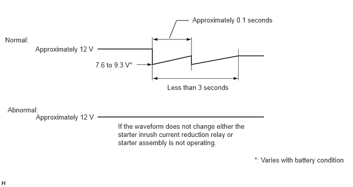
- Standard:
Waveform drops 2 times
- Result:
Number of Times Waveform Dropped Proceed to 0 times A 2 times B
A
B
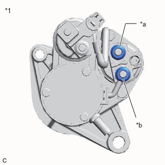
| *1 | Starter Assembly |
| *a | B Terminal |
| *b | M Terminal |
Disconnect the cable from the negative (-) battery terminal.
Disconnect terminals B and M of the starter inrush current reduction relay.
Measure the resistance according to the value(s) in the table below.
- Standard Resistance:
Tester Connection Condition Specified Condition B Terminal - M Terminal Always Below 1 Ω
- Result:
Proceed to OK NG
OK
NG
Disconnect the cable from the negative (-) battery terminal.
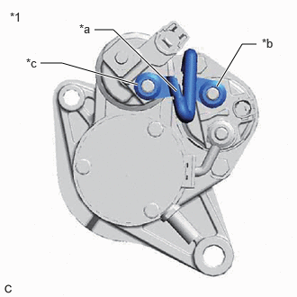
| *1 | Starter Assembly |
| *a | Inspect Part |
| *b | C Terminal |
| *c | B Terminal |
Disconnect terminal B of the starter inrush current reduction relay.
Disconnect terminal C of the starter assembly.
Measure the resistance according to the value(s) in the table below.
- Standard Resistance:
Tester Connection Condition Specified Condition C Terminal - B Terminal Always Below 1 Ω
- Result:
Proceed to OK NG
OK
NG
Disconnect the cable from the negative (-) battery terminal.
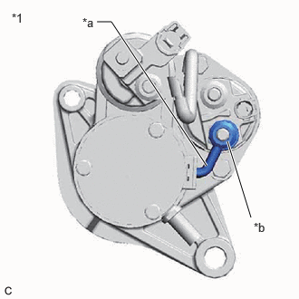
| *1 | Starter Assembly |
| *a | Inspect Part |
| *b | M Terminal |
Disconnect terminal M of the starter inrush current reduction relay.
Measure the resistance according to the value(s) in the table below.
- Standard Resistance:
Tester Connection Condition Specified Condition M Terminal - Body ground Always Below 1 Ω
- Result:
Proceed to OK NG
OK
NG
- Result:
Proceed to OK NG
OK
NG
Disconnect the engine stop and start ECU connectors.
Measure the voltage according to the value(s) in the table below.
- Standard Voltage:
Tester Connection Condition Specified Condition Click Location & Routing(A105)Location & Routingewd_type=routing;type=c;code=A105
Click Connector(A105)Instrument Panel>Engine Room Main Wire>Engine Stop and Start ECUewd_type=component;type=c;code=A105;pinno=1,3
A105-1 (BIN2) - Body ground Always 9.5 to 14 V A105-3 (BIN1) - Body ground Always 9.5 to 14 V
Turn the ignition switch to ON.
Measure the voltage according to the value(s) in the table below.
- Standard Voltage:
Tester Connection Condition Specified Condition Click Location & Routing(A106,A104)Location & Routingewd_type=routing;type=c,c;code=A106,A104
Click Connector(A106)Instrument Panel>Engine Room Main Wire>Engine Stop and Start ECUewd_type=component;type=c;code=A106;pinno=1
Click Connector(A104)Instrument Panel>Engine Room Main Wire>Engine Stop and Start ECUewd_type=component;type=c;code=A104;pinno=21,18
A106-1 (+B) - Body ground Ignition switch ON 9.5 to 14 V A104-21 (IGR) - Body ground Ignition switch ON 9.5 to 14 V A104-18 (IGP) - Body ground Ignition switch ON 9.5 to 14 V
- Result:
Proceed to OK NG
OK
NG
Disconnect the engine stop and start ECU connectors.
Measure the resistance according to the value(s) in the table below.
- Standard Resistance:
Tester Connection Condition Specified Condition Click Location & Routing(A105,A106)Location & Routingewd_type=routing;type=c,c;code=A105,A106
Click Connector(A105)Instrument Panel>Engine Room Main Wire>Engine Stop and Start ECUewd_type=component;type=c;code=A105;pinno=2,8
Click Connector(A106)Instrument Panel>Engine Room Main Wire>Engine Stop and Start ECUewd_type=component;type=c;code=A106;pinno=6
A105-2 (GND2) - Body ground Always Below 1 Ω A105-8 (GND1) - Body ground Always Below 1 Ω A106-6 (DGND) - Body ground Always Below 1 Ω
- Result:
Proceed to OK NG
OK
- HINT:
-
If arriving at this item from the item "Drive command is being sent from the engine stop and start ECU but the starter itself is not moving" of "After Engine Stops due to Stop and Start System, Engine does not Restart" in Stop and Start / Stop and Start System / Problem Symptoms Table, go to SIMULATION METHOD.
NG