M20C-FKS, M20D-FKS STARTING STARTER(for 1.2 kW Type) INSPECTION
PROCEDURE

 28100
1.INSPECT STARTER ASSEMBLY
28100
1.INSPECT STARTER ASSEMBLY
- CAUTION:
-
As a large electric current passes through the cable during this inspection, a thick cable must be used. If not, the cable may become hot and cause injury.
- NOTICE:
-
Perform each of the following tests within 3 to 5 seconds to prevent the coil from burning out.
Perform a pull-in test.
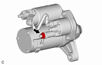
Remove the nut, and disconnect the lead wire from terminal M.
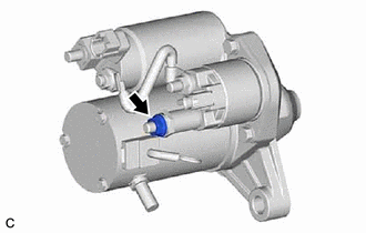
Once again, install and fasten the removed nut to the terminal M.
- HINT:
-
Make sure the contact area of the terminal M is not floating.

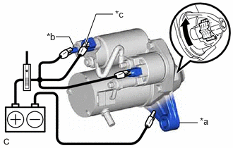
| *a | Starter Body |
| *b | Terminal 50 |
| *c | Terminal C |

|
Moves outward |
Connect a battery to the magnet starter switch assembly as shown in the illustration. Check that the clutch pinion gear moves outward.
If the clutch pinion gear does not move outward, replace the magnet starter switch assembly.
Perform a hold-in test.
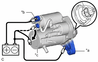
| *a | Starter Body |
| *b | Terminal 50 |
| *c | Terminal C |
|
|
Disconnect |
While maintaining the battery connections of the pull-in test, disconnect the negative (-) lead from terminal C. Check that the clutch pinion gear does not return inward.
If the clutch pinion gear returns inward, replace the magnet starter switch assembly.
Perform a return test.
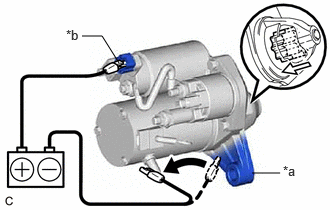
| *a | Starter Body |
| *b | Terminal 50 |
|
|
Disconnect |

|
Returns inward |
Disconnect the negative (-) lead from the starter body. Check that the clutch pinion gear returns inward.
If the clutch pinion gear does not return inward, replace the magnet starter switch assembly.
Perform a no-load performance test.
Connect the lead wire to terminal M with the nut. Make sure that the lead wire is not grounded.
- Torque:
- 9.0 N*m (92 kgf*cm, 80 in.*lbf)
Secure the starter assembly in a vise between aluminum plates.
- NOTICE:
-
Ensure that the starter assembly is secured in the vise to prevent it from falling out.
| *a | Starter Body |
| *b | Terminal 30 |
| *c | Terminal 50 |
|
|
Rotates |
Connect the battery and an ammeter to the starter assembly as shown in the illustration.
- NOTICE:
-
Do not allow any lead to get caught as the clutch pinion gear operates.
Check that the starter assembly operates smoothly and steadily while the clutch pinion gear is moving outward.
Measure the current according to the value(s) in the table below.
- Standard Current:
Tester Connection Condition Specified Condition Battery positive (+) terminal - Terminal 30 - Terminal 50 11.5 V Below 90 A
If the result is not as specified, replace the starter assembly.
28160
2.INSPECT STARTER ARMATURE ASSEMBLY
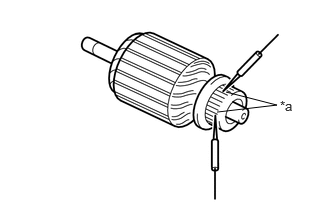
| *a | Segment |
Check the commutator for an open circuit.
Measure the resistance according to the value(s) in the table below.
- Standard Resistance:
Tester Connection Condition Specified Condition Segment - Segment Always Below 1 Ω
If the result is not as specified, replace the starter armature assembly.
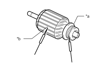
| *a | Segment |
| *b | Starter Armature Core |
Check the commutator for a short circuit.
Measure the resistance according to the value(s) in the table below.
- Standard Resistance:
Tester Connection Condition Specified Condition Segment - Starter armature core Always 10 kΩ or higher
If the result is not as specified, replace the starter armature assembly.
Check the commutator appearance.
If the surface is dirty or burnt, replace the starter armature assembly.
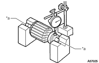
| *a | Armature Shaft |
Check the commutator for runout.
Place the armature shaft on V-blocks.
Using a dial indicator, measure the runout.
- Maximum Runout:
0.05 mm (0.00197 in.)
If the runout is greater than the maximum, replace the starter armature assembly.
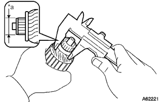
| *a | Diameter |
Using a vernier caliper, measure the commutator diameter.
- Standard Diameter:
25 mm (0.984 in.)
- Minimum Diameter:
24 mm (0.945 in.)
If the diameter is less than the minimum, replace the starter armature assembly.
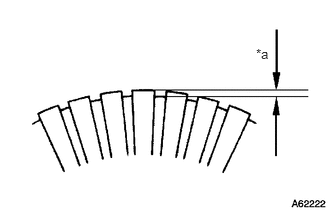
| *a | Undercut Depth |
Check that the undercut portion between the segments is free of foreign matter and measure its depth.
- Standard Undercut Depth:
0.7 mm (0.0276 in.)
- Minimum Undercut Depth:
0.2 mm (0.00787 in.)
If the undercut depth is less than the minimum, replace the starter armature assembly.
28140
3.INSPECT STARTER BRUSH HOLDER ASSEMBLY
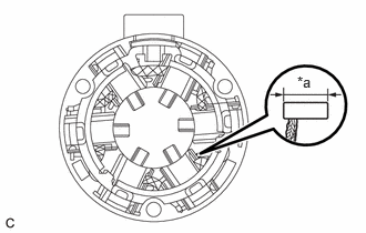
| *a | Length |
Check the brush length.
Using a vernier caliper, measure the brush length.
- Standard Length:
11.6 mm (0.457 in.)
- Minimum Length:
7.6 mm (0.299 in.)
If the length is less than the minimum, replace the starter brush holder assembly.
28021
4.INSPECT STARTER CENTER BEARING CLUTCH SUB-ASSEMBLY
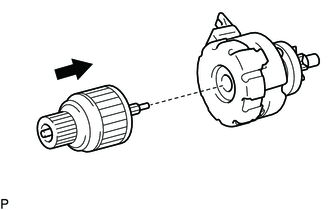
Install the starter armature assembly to the starter center bearing clutch sub-assembly.
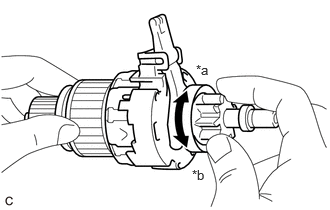
| *a | Free |
| *b | Lock |
Hold the starter armature assembly, rotate the clutch pinion gear clockwise, and check that it turns freely. Try to rotate the clutch pinion gear counterclockwise and check that it locks. If the clutch pinion gear does not operate as specified, replace the starter center bearing clutch sub-assembly.
28150
5.INSPECT MAGNET STARTER SWITCH ASSEMBLY
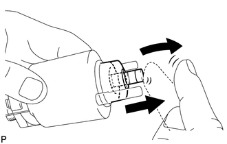
Check the plunger.
Push in the plunger and check that it returns quickly to its original position.
If the plunger does not operate as specified, replace the magnet starter switch assembly.
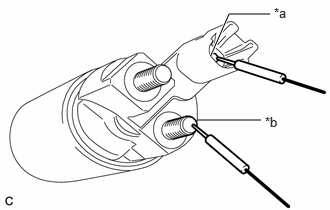
| *a | Terminal 50 |
| *b | Terminal C |
Check the pull-in coil for an open circuit.
Measure the resistance according to the value(s) in the table below.
- Standard Resistance:
Tester Connection Condition Specified Condition Terminal 50 - Terminal C Always Below 1 Ω
If the result is not as specified, replace the magnet starter switch assembly.
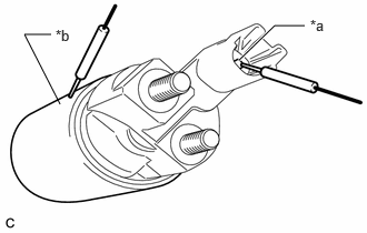
| *a | Terminal 50 |
| *b | Magnet Starter Switch Assembly Body |
Check the holding coil for an open circuit.
Measure the resistance according to the value(s) in the table below.
- Standard Resistance:
Tester Connection Condition Specified Condition Terminal 50 -Magnet starter switch assembly body Always Below 2 Ω
If the result is not as specified, replace the magnet starter switch assembly.