M20C-FKS, M20D-FKS ENGINE MECHANICAL ENGINE ASSEMBLY INSTALLATION
CAUTION / NOTICE / HINT
- CAUTION:
- ·
The engine assembly with transaxle is very heavy. Be sure to follow the procedure described in the repair manual, or the engine lifter may suddenly drop or the engine assembly with transaxle may fall off the engine lifter.
·To prevent burns, do not touch the engine, exhaust manifold or other high temperature components while the engine is hot.
PROCEDURE

 12372A
1.INSTALL ENGINE MOUNTING INSULATOR LH
12372A
1.INSTALL ENGINE MOUNTING INSULATOR LH
- HINT:
-
Perform this procedure only when replacement of the engine mounting insulator LH is necessary.
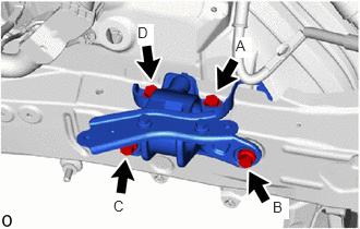
Install the engine mounting insulator LH to the vehicle body with the 4 bolts.
- Torque:
- 72 N*m (734 kgf*cm, 53 ft.*lbf)
- NOTICE:
-
Temporarily tighten the bolt (A), and then fully tighten the 4 bolts in the order of (B), (C), (D) and (A).
12341
2.INSTALL ENGINE MOUNTING SPACER
- HINT:
-
Perform this procedure only when replacement of the engine mounting spacer is necessary.
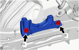
Install the engine mounting spacer to the vehicle body with the 2 bolts.
- Torque:
- 72 N*m (734 kgf*cm, 53 ft.*lbf)
- NOTICE:
-
Temporarily tighten the bolt (A), and then fully tighten the 2 bolts in the order of (B) and (A).
12305
3.INSTALL ENGINE MOUNTING INSULATOR SUB-ASSEMBLY RH
- HINT:
-
Perform this procedure only when replacement of the engine mounting insulator sub-assembly RH is necessary.
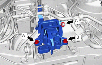
Install the engine mounting insulator sub-assembly RH with the 2 bolts and nut.
- Torque:
- 72 N*m (734 kgf*cm, 53 ft.*lbf)
- NOTICE:
-
Temporarily tighten the bolt (A), and then fully tighten the 2 bolts and nut in the order of (B), (A) and (C).
Install the No. 2 earth wire to the engine mounting insulator sub-assembly RH with the bolt.
- Torque:
- 10 N*m (102 kgf*cm, 7 ft.*lbf)
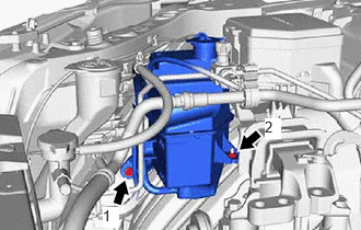
Install the radiator reserve tank assembly with the bolt and nut in the order shown in the illustration.
- Torque:
- 5.0 N*m (51 kgf*cm, 44 in.*lbf)
Engage the 2 clamps.
4.INSTALL ENGINE HANGERS
5.REMOVE ENGINE ASSEMBLY FROM ENGINE STAND
Remove the engine assembly from the engine stand.
82121
6.INSTALL ENGINE WIRE
Install the engine wire to the engine assembly.
19315
7.INSTALL NO. 1 CRANKSHAFT POSITION SENSOR PLATE
32101B
8.INSTALL DRIVE PLATE AND RING GEAR SUB-ASSEMBLY
9.INSTALL ENGINE ASSEMBLY
37117
10.INSTALL PROPELLER SHAFT HEAT INSULATOR (for AWD)
11.INSTALL WIRE HARNESS CLAMP BRACKET
28100
12.INSTALL STARTER ASSEMBLY
11363A
13.INSTALL FLYWHEEL HOUSING SIDE COVER
12371A
14.INSTALL REAR ENGINE MOUNTING INSULATOR
- HINT:
-
Perform this procedure only when replacement of the rear engine mounting insulator is necessary.
12361
15.INSTALL FRONT ENGINE MOUNTING INSULATOR
- HINT:
-
Perform this procedure only when replacement of the front engine mounting insulator is necessary.
Install the front engine mounting insulator to the front frame assembly with the 3 nuts.
- Torque:
- 72 N*m (734 kgf*cm, 53 ft.*lbf)
12311A
16.INSTALL FRONT ENGINE MOUNTING BRACKET
51100G
17.INSTALL FRONT FRAME ASSEMBLY
Install the rear engine mounting insulator to the front frame assembly with the 4 nuts.
- Torque:
- 72 N*m (734 kgf*cm, 53 ft.*lbf)
Install the front engine mounting insulator to the front engine mounting bracket with the bolt.
- Torque:
- 72 N*m (734 kgf*cm, 53 ft.*lbf)
Engage the wire harness clamp to connect the vacuum switching valve (for active control engine mount system) connector.
18.CONNECT ENGINE WIRE
19.INSTALL WATER BY-PASS PIPE SUB-ASSEMBLY
Install the water by-pass pipe sub-assembly with the 3 bolts.
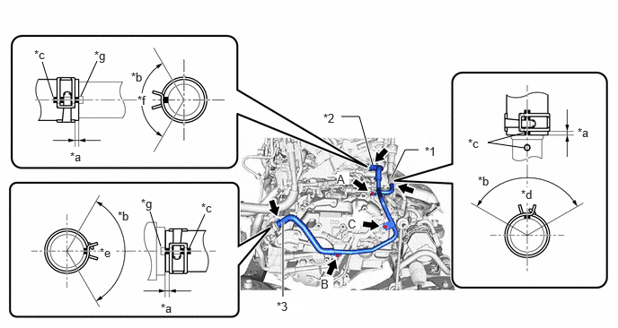
| *1 | Water By-pass Hose Assembly | *2 | No. 3 Water By-pass Hose |
| *3 | No. 4 Water By-pass Hose | - | - |
| *a | 2 to 7 mm (0.0787 to 0.276 in.) | *b | 120° |
| *c | Paint Mark | *d | Rear Side of Vehicle |
| *e | Upper Side | *f | RH Side of Vehicle |
| *g | Protrusion | - | - |
- Torque:
- 10 N*m (102 kgf*cm, 7 ft.*lbf)
- NOTICE:
-
Temporarily tighten the bolt (A), and then fully tighten the 3 bolts in the order of (B), (C) and (A).
Connect the water by-pass hose assembly, No. 3 water by-pass hose and No. 4 water by-pass hose and slide the 3 clips to secure them.
- NOTICE:
- ·
Make sure to slide the water by-pass hose assembly, No. 3 water by-pass hose and No. 4 water by-pass hose until they contact the hose stoppers.
·Make sure that the claws of the clip are within the location shown in the illustration.
20.CONNECT VACUUM HOSE
for 2WD:
Engage the 5 clamps.
Connect the vacuum hose to the rear engine mounting insulator.
for AWD:
Engage the 3 clamps.
16261G
21.INSTALL NO. 1 WATER BY-PASS HOSE
Install the No. 1 water by-pass hose and slide the 2 clips to secure it.
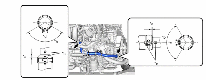
| *a | 2 to 7 mm (0.0787 to 0.276 in.) | *b | 120° |
| *c | Paint Mark | *d | LH Side of Vehicle |
| *e | Upper Side | - | - |
- NOTICE:
- ·
Make sure to slide the No. 1 water by-pass hose until it contacts the hose stopper.
·Make sure that the claws of the clip are within the location shown in the illustration.
Engage the 2 clamps.
32101G
22.INSTALL DRIVE PLATE AND TORQUE CONVERTER ASSEMBLY SETTING BOLT
11361J
23.INSTALL FLYWHEEL HOUSING UNDER COVER
24.INSTALL EMISSION CONTROL VALVE BRACKET
89481B
25.INSTALL DIFFERENTIAL PRESSURE SENSOR
26.INSTALL ENGINE ASSEMBLY WITH TRANSAXLE
- HINT:
-
Perform "Inspection After Repair" after replacing the engine assembly.
Set the engine assembly with transaxle on an engine lifter.
- NOTICE:
- ·
Using height adjustment attachments and plate lift attachments, keep the engine assembly with transaxle level.
·Do not perform any procedures while the engine assembly is suspended because doing so may cause the engine assembly to drop, resulting in injury. However, the engine assembly needs to be suspended when it is installed to or removed from an engine stand.
Remove the 4 bolts, No. 1 engine hanger and No. 2 engine hanger.
Install the fuel delivery guard to the engine mounting bracket RH with the bolt.
- Torque:
- 40 N*m (408 kgf*cm, 30 ft.*lbf)
Operate the engine lifter and install the engine assembly with transaxle to the vehicle.
- CAUTION:
-
Do not raise the engine assembly with transaxle more than necessary. If the engine is raised excessively, the vehicle may also be lifted up.
- NOTICE:
- ·
Make sure that the engine assembly with transaxle is clear of all wiring and hoses.
·While raising the engine assembly with transaxle into the vehicle, do not allow it to contact the vehicle.
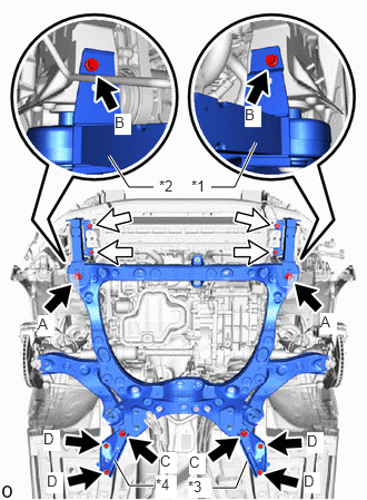
| *1 | Front Bumper Extension Sub-assembly LH |
| *2 | Front Bumper Extension Sub-assembly RH |
| *3 | Rear Front Suspension Member Brace LH |
| *4 | Rear Front Suspension Member Brace RH |

|
Bolt |

|
Nut |
Install the front bumper extension sub-assembly LH and front bumper extension sub-assembly RH to the front frame assembly and vehicle body with the 2 bolts (A), 2 bolts (B) and 4 nuts.
- Torque:
- Bolt (A) : 135 N*m (1377 kgf*cm, 100 ft.*lbf)
- Bolt (B) : 9.5 N*m (97 kgf*cm, 84 in.*lbf)
- Nut : 12.5 N*m (127 kgf*cm, 9 ft.*lbf)
Install the rear front suspension member brace LH and rear front suspension member brace RH to the front frame assembly and vehicle body with the 2 bolts (C) and 4 bolts (D).
- Torque:
- Bolt (C) : 135 N*m (1377 kgf*cm, 100 ft.*lbf)
- Bolt (D) : 60 N*m (612 kgf*cm, 44 ft.*lbf)
Install the engine mounting insulator LH to the engine mounting bracket sub-assembly LH with the bolt and nut.
- Torque:
- 42 N*m (428 kgf*cm, 31 ft.*lbf)
Install the engine mounting insulator sub-assembly RH to the engine mounting bracket RH with the 3 bolts and nut.
- Torque:
- Bolt : 72 N*m (734 kgf*cm, 53 ft.*lbf)
- Nut : 42 N*m (428 kgf*cm, 31 ft.*lbf)
37110
27.INSTALL PROPELLER SHAFT WITH CENTER BEARING ASSEMBLY (for AWD)
28.INSTALL FRONT DRIVE SHAFT ASSEMBLY
17410
29.INSTALL FRONT EXHAUST PIPE ASSEMBLY (TWC: Rear Catalyst)
45220
30.CONNECT STEERING INTERMEDIATE SHAFT ASSEMBLY
16282F
31.CONNECT NO. 5 WATER BY-PASS HOSE
Connect the No. 5 water by-pass hose to the No. 3 water by-pass pipe and slide the clip to secure it.
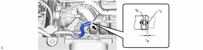
| *a | 2 to 7 mm (0.0787 to 0.276 in.) | *b | Paint Mark |
| *c | Protrusion | - | - |
- NOTICE:
-
Make sure to slide the No. 5 water by-pass hose until it contacts the hose stopper.
32.CONNECT WIRE HARNESS
Engage the clamp to connect the wire harness to the vehicle body.
Install the bolt.
- Torque:
- 8.0 N*m (82 kgf*cm, 71 in.*lbf)
Engage the clamp to connect the wire harness to the continuously variable transaxle assembly.
Install the bolt.
- Torque:
- 20 N*m (204 kgf*cm, 15 ft.*lbf)
Engage the claw to connect the wire harness to the No. 1 engine room relay block assembly and No. 1 engine room junction block assembly.
Connect the 5 connectors to the No. 1 engine room relay block assembly and No. 1 engine room junction block assembly.
Connect the wire harness to the No. 1 engine room relay block assembly and No. 1 engine room junction block assembly with the nut.
- Torque:
- 8.0 N*m (82 kgf*cm, 71 in.*lbf)
Install the No. 1 relay block cover to the No. 1 engine room relay block assembly and No. 1 engine room junction block assembly.
88711
33.CONNECT NO. 1 COOLER REFRIGERANT DISCHARGE HOSE
88704
34.CONNECT SUCTION HOSE SUB-ASSEMBLY
16572D
35.CONNECT NO. 2 RADIATOR HOSE
Connect the No. 2 radiator hose to the water inlet with thermostat sub-assembly and slide the clip to secure it.
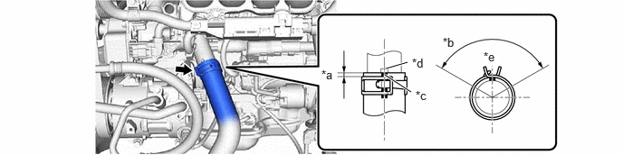
| *a | 2 to 7 mm (0.0787 to 0.276 in.) | *b | 120° |
| *c | Paint Mark | *d | Protrusion |
| *e | Upper Side | - | - |
- NOTICE:
- ·
Make sure to slide the No. 2 radiator hose until it contacts the hose stopper.
·Make sure that the claws of the clip are within the location shown in the illustration.
16571C
36.CONNECT NO. 1 RADIATOR HOSE
Connect the No. 1 radiator hose to the water outlet and slide the clip to secure it.
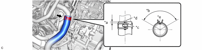
| *a | 2 to 7 mm (0.0787 to 0.276 in.) | *b | 120° |
| *c | Paint Mark | *d | Protrusion |
| *e | Upper Side | - | - |
- NOTICE:
- ·
Make sure to slide the No. 1 radiator hose until it contacts the hose stopper.
·Make sure that the claws of the clip are within the location shown in the illustration.
23901
37.CONNECT FUEL TUBE SUB-ASSEMBLY
Connect the fuel tube sub-assembly to the fuel pipe.
Install the No. 1 fuel pipe clamp to the fuel tube connector.
87245
38.CONNECT INLET HEATER WATER HOSE
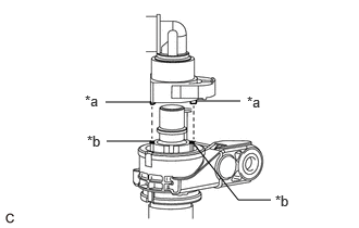
| *a | Protrusion |
| *b | Cutout |
Align the protrusions of the inlet heater water hose connector with the cutouts in the flow shutting valve (water by-pass hose assembly) and push them together until the inlet heater water hose connector makes a "click" sound.
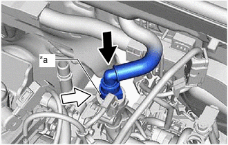
| *a | Retainer |
|
|
Push |
|
|
Push in |
Push in the retainer.
Check that the flow shutting valve (water by-pass hose assembly) and inlet heater water hose connector are securely connected by pulling on them.
87246
39.CONNECT OUTLET HEATER WATER HOSE
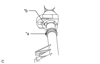
| *a | Protrusion |
| *b | Cutout |
Align the protrusion of the No. 2 water by-pass pipe sub-assembly with the cutout in the outlet heater water hose connector and push them together until the outlet heater water hose connector makes a "click" sound.
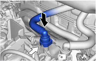
| *a | Retainer |
|
|
Push |
|
|
Push in |
Push in the retainer.
Check that the No. 2 water by-pass pipe sub-assembly and outlet heater water hose connector are securely connected by pulling on them.
44777
40.CONNECT NO. 1 VACUUM HOSE CONNECTOR
Connect the No. 1 vacuum hose connector to the vacuum pump assembly.
Engage the clamp.
23826
41.CONNECT NO. 1 FUEL VAPOR FEED HOSE
Connect the No. 1 fuel vapor feed hose to the purge valve (purge VSV) and slide the clip to secure it.
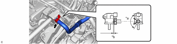
| *a | 120° | *b | 2 to 7 mm (0.0787 to 0.276 in.) |
- NOTICE:
-
Make sure that the claws of the clip are within the location shown in the illustration.
33820B
42.CONNECT TRANSMISSION CONTROL CABLE ASSEMBLY
- NOTICE:
-
Before connecting the transmission control cable assembly, check that the shift lever is in N.
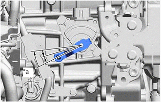
| *a | N |
Turn the transmission control shaft lever clockwise until it stops, then turn it counterclockwise 2 notches.
- NOTICE:
-
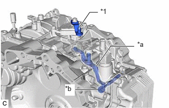 1.615,0.552 1.823,0.25 1.823,0.25 1.99,0.25 true 1.958,1.344 2.25,0.938 2.25,0.938 2.729,0.938 true 1.531,1.813 1.99,1.813 true 2.042,0.146 2.323,0.385 0.281,0.24 10 false *1 2.792,0.813 3.073,1.052 0.281,0.24 10 false *a 1.323,1.708 1.521,1.938 0.198,0.229 10 true *b
*1 Transmission Control Shaft Lever *a Manual Valve Link Lever Sub-assembly *b Manual Valve
-
If the transmission control shaft lever is turned counterclockwise more than necessary, manual valve link lever sub-assembly may separate from the manual valve.
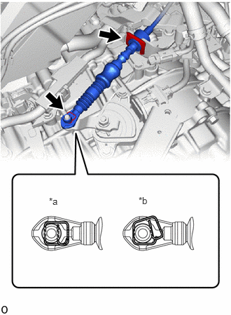
| *a | Correct |
| *b | Incorrect |
Connect the transmission control cable assembly to the No. 1 transmission control cable bracket with a new clip.
Connect the transmission control cable assembly to the transmission control shaft lever as shown in the illustration.
74404B
43.INSTALL BATTERY CLAMP SUB-ASSEMBLY
Install the battery clamp sub-assembly with the 3 bolts.
- Torque:
- 18.5 N*m (189 kgf*cm, 14 ft.*lbf)
Engage the 2 claws and connect the engine room main wire to the No. 2 engine wire.
Connect the engine room main wire and No. 2 engine wire to the positive (+) battery terminal with the nut.
- Torque:
- 7.5 N*m (76 kgf*cm, 66 in.*lbf)
Engage the 2 clamps to connect the engine room main wire and No. 2 engine wire to the battery clamp sub-assembly.
Engage the 2 clamps to the battery clamp sub-assembly.
89661
44.INSTALL ECM
45.INSTALL AIR CLEANER ASSEMBLY WITH AIR CLEANER HOSE
17750A
46.INSTALL INLET AIR CLEANER ASSEMBLY
12601B
47.INSTALL NO. 1 ENGINE COVER SUB-ASSEMBLY
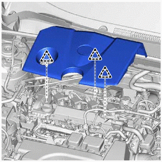
Align the center of the grommet hole of the No. 1 engine cover sub-assembly with the oil filler cap assembly, then align the 3 clips and install the No. 1 engine cover sub-assembly.
- NOTICE:
- ·
Securely engage the clips.
·If the clips are forcibly engaged or struck with an object, they may be damaged.
48.INSPECT VACUUM HOSES
Inspect the vacuum hoses.
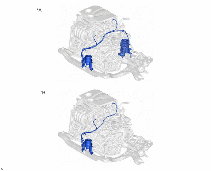
| *A | for 2WD | *B | for AWD |
49.INSTALL BATTERY
50.INSPECT SHIFT LEVER POSITION
51.ADJUST SHIFT LEVER POSITION
52.ADD ENGINE OIL
53.ADD TRANSFER OIL (for AWD)
54.ADD ENGINE COOLANT
55.ADJUST CONTINUOUSLY VARIABLE TRANSAXLE FLUID
56.CHARGE AIR CONDITIONING SYSTEM WITH REFRIGERANT
57. WARM UP ENGINE
58.INSPECT FOR FUEL LEAK
59.INSPECT FOR ENGINE OIL LEAK
60.INSPECT FOR COOLANT LEAK
61.INSPECT FOR CONTINUOUSLY VARIABLE TRANSAXLE FLUID LEAKS
62.INSPECT FOR REFRIGERANT LEAK
63.INSPECT FOR EXHAUST GAS LEAK
64.CHECK ENGINE OIL LEVEL
65.INSPECT ENGINE COOLANT LEVEL IN RESERVOIR TANK
52618
66.INSTALL FRONT BUMPER LOWER ABSORBER
for SFTM Made: Click hereVehicle Exterior>EXTERIOR PANELS / TRIM>FRONT BUMPER (for SFTM Made)>REASSEMBLY202111,999999,_59,_111849,_0500095,RM100000001Z1C3_01_0386,
for GTMC Made: Click hereVehicle Exterior>EXTERIOR PANELS / TRIM>FRONT BUMPER (for GTMC Made)>REASSEMBLY202203,999999,_59,_111849,_0524334,RM1000000022091_01_0386,
67.INSTALL FRONT BUMPER ASSEMBLY
for SFTM Made: Click hereVehicle Exterior>EXTERIOR PANELS / TRIM>FRONT BUMPER (for SFTM Made)>INSTALLATION202303,999999,_59,_111849,_0500095,RM100000002AYNL,
for GTMC Made: Click hereVehicle Exterior>EXTERIOR PANELS / TRIM>FRONT BUMPER (for GTMC Made)>INSTALLATION202303,999999,_59,_111849,_0524334,RM100000002AYND,
58166A
68.INSTALL FRONT FLOOR COVER LH
58165C
69.INSTALL FRONT FLOOR COVER RH
53737B
70.INSTALL FRONT FENDER APRON SEAL LH
Install the front fender apron seal LH with the 2 bolts and clip.
- Torque:
- 7.5 N*m (76 kgf*cm, 66 in.*lbf)
53736
71.INSTALL FRONT FENDER APRON SEAL RH
Install the front fender apron seal RH with the 2 bolts and clip.
- Torque:
- 7.5 N*m (76 kgf*cm, 66 in.*lbf)
51420
72.INSTALL NO. 2 ENGINE UNDER COVER ASSEMBLY
Install the No. 2 engine under cover assembly with the 2 bolts, 2 screws and 6 clips.
- Torque:
- Bolt : 7.5 N*m (76 kgf*cm, 66 in.*lbf)
51441
73.INSTALL NO. 1 ENGINE UNDER COVER
Install the No. 1 engine under cover with the 2 bolts and 6 screws.
- Torque:
- Bolt : 7.5 N*m (76 kgf*cm, 66 in.*lbf)
53896B
74.INSTALL FRONT FENDER FRONT SPLASH SHIELD LH
Install the front fender front splash shield LH with the 3 screws.
53895B
75.INSTALL FRONT FENDER FRONT SPLASH SHIELD RH
Install the front fender front splash shield RH with the 3 screws.
76.INSTALL FRONT WHEELS
77. ALIGN FRONT WHEELS FACING STRAIGHT AHEAD
78.INSPECT AND ADJUST FRONT WHEEL ALIGNMENT
79.PERFORM INITIALIZATION
80.INSPECT IGNITION TIMING
81.INSPECT ENGINE IDLE SPEED
82.INSPECT CO/HC
83.CHECK SPEED SENSOR SIGNAL
84. INITIALIZATION AFTER RECONNECTING BATTERY TERMINAL
- HINT:
-
When disconnecting and reconnecting the battery, there is an automatic learning function that completes learning when the respective system is used.