DRIVE SHAFT / PROPELLER SHAFT PROPELLER SHAFT ASSEMBLY INSTALLATION
PROCEDURE

 37100
1.TEMPORARILY INSTALL PROPELLER SHAFT WITH CENTER BEARING ASSEMBLY
37100
1.TEMPORARILY INSTALL PROPELLER SHAFT WITH CENTER BEARING ASSEMBLY
Completely remove any oil or the like and clean the contact surfaces of the rear transfer output shaft sub-assembly and propeller shaft with center bearing assembly.
Completely remove any oil or the like and clean the contact surfaces of the transmission coupling assembly and propeller shaft with center bearing assembly.
Align the matchmarks of the transfer assembly and propeller shaft with center bearing assembly.
Temporarily install the propeller shaft with center bearing assembly with the 4 nuts and 4 washers.
Align the matchmarks of the differential carrier assembly and propeller shaft with center bearing assembly.
Temporarily install the propeller shaft with center bearing assembly with the 4 nuts and 4 washers.
Temporarily install the center support bearing and center No. 2 support bearing washer with the 2 bolts.
37100
2.TIGHTEN PROPELLER SHAFT WITH CENTER BEARING ASSEMBLY
Tighten the 4 nuts of the propeller shaft with center bearing assembly and transfer assembly to the torque specification.
- Torque:
- 35 N*m (357 kgf*cm, 26 ft.*lbf)
Tighten the 4 nuts of the propeller shaft with center bearing assembly and differential carrier assembly to the torque specification.
- Torque:
- 35 N*m (357 kgf*cm, 26 ft.*lbf)
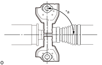
| *a | 90° |
Check that the center line of the center support bearing housing is perpendicular to the axis of the propeller shaft.
Tighten the 2 bolts of the center support bearing to the torque specification.
- Torque:
- 36.8 N*m (375 kgf*cm, 27 ft.*lbf)
3.INSPECT AND ADJUST JOINT ANGLE
- NOTICE:
-
Perform the measurement with a 4 post lift or pit so that the vehicle is supported by all 4 wheels as if it were on the ground.
Before the angle measurement, stabilize each part by performing procedures like those described below.
Rotate the propeller shaft several times by hand.
Set the jack to the differential, and raise and lower the differential.
Using SST and a straightedge, measure the angle of the transfer flange (angle D) and the angle of the intermediate shaft (angle A).
- SST
- 09370-50010
- NOTICE:
-
Make sure the straightedge and SST are at a right angle.
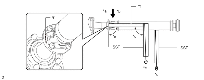
| *1 | Straightedge | - | - |
| *a | No. 1 Joint Angle | *b | D - A |
| *c | 90° | *d | Angle A |
| *e | Angle D | *f | Angle D Measurement Position |
Subtract the measured angle of the intermediate shaft (angle A) from the measured angle of the transfer flange (angle D) to obtain the No. 1 joint angle.
- No. 1 Joint Angle:
Measurement Position No. 1 Joint Angle No. 1 Joint Angle (D - A) -2°13' +/- 60'
Using SST, measure the angle of the intermediate shaft (angle A) and the angle of the propeller shaft (angle B).
- SST
- 09370-50010
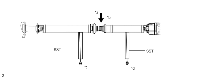
| *a | No. 2 Joint Angle | *b | A - B |
| *c | Angle A | *d | Angle B |
Subtract the measured angle of the propeller shaft (angle B) from the measured angle of the intermediate shaft (angle A) to obtain the No. 2 joint angle.
- No. 2 Joint Angle:
Measurement Position No. 2 Joint Angle No. 2 Joint Angle (A - B) 0°23' +/- 60'
Using SST, measure the angle of the propeller shaft (angle B) and the angle of the rear differential (angle C).
- SST
- 09370-50010
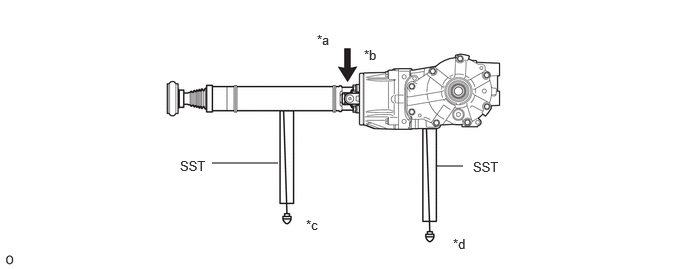
| *a | No. 3 Joint Angle | *b | B - C |
| *c | Angle B | *d | Angle C |
Subtract the measured angle of the propeller shaft (angle B) from the measured angle of the rear differential (angle C) to obtain the No. 3 joint angle.
- No. 3 Joint Angle:
Measurement Position No. 3 Joint Angle No. 3 Joint Angle (B - C) 1°49' +/- 60'
If the measured angle of the propeller shaft is not within the specified range, or there is vibration or noise, use the following procedure to adjust the propeller shaft.
Support the propeller shaft with a jack.
Remove the 2 center bearing mounting bolts.
Slowly lower the jack and disconnect the center bearing.
Select an appropriate adjusting washer thickness from the table below, and obtain a washer set.
- Standard Adjusting Washer:
Thickness 2.0 mm (0.0787 in.) 4.5 mm (0.1772 in.) 6.5 mm (0.2559 in.)
- HINT:
- ·
Use washers of the same thickness on the left and right sides.
·Do not use 2 or more washers stacked together.
·Install the washers.
58152A
4.INSTALL LOWER NO. 1 FRONT FLOOR HEAT INSULATOR
Install the lower No. 1 front floor heat insulator with the 3 nuts.
- Torque:
- 4.9 N*m (50 kgf*cm, 43 in.*lbf)
17410
5.INSTALL FRONT EXHAUST PIPE ASSEMBLY
58398F
6.INSTALL NO. 1 FLOOR UNDER COVER
58165C
7.INSTALL FRONT FLOOR COVER RH
58399D
8.INSTALL NO. 2 FLOOR UNDER COVER
58166A
9.INSTALL FRONT FLOOR COVER LH