K120 / K120F / K121 / K121F CVT CONTINUOUSLY VARIABLE TRANSAXLE FLUID ADJUSTMENT
CAUTION / NOTICE / HINT
The necessary procedures (adjustment, calibration, initialization or registration) that must be performed after parts are removed and installed, or replaced during CVT fluid adjustment are shown below.
| Replaced Part or Performed Procedure | Necessary Procedure | Effect/Inoperative Function when Necessary Procedure not Performed | Link |
|---|---|---|---|
| Replacement of CVT fluid | Air bleed the oil pump with motor assembly | Stop and Start System | ( 202111,999999,_51,_111803,_0509671,RM1000000020651,) 202111,999999,_51,_111803,_0509671,RM1000000020651,)
|
| ATF thermal degradation estimate reset | The value of the Data List item "ATF Thermal Degradation Estimate" is not estimated correctly | (202303,999999,_52,_111806,_0584611,RM1000000029R1M,)
|
- CAUTION:
- ·
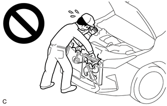
To prevent injury due to contact with an operating V-ribbed belt or cooling fan, keep your hands and clothing away from the V-ribbed belt and cooling fan when working in the engine compartment with the engine running or the ignition switch ON.
PROCEDURE

 1. PRECAUTIONS AND WORK DESCRIPTION
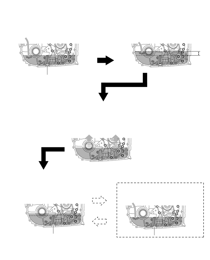
The K120 / K120F / K121 / K121F continuously variable transaxle assembly does not have an oil filler tube or oil level gauge. When adding fluid, add fluid through the refill plug hole in the continuously variable transaxle assembly. The fluid level can be adjusted by draining excess fluid (allowing excess fluid to overflow) through the overflow (CVT) tube of the transaxle case sub-assembly.
- HINT:
-
"Overflow" indicates the condition under which fluid comes out of the overflow plug hole.
When adding fluid, add the specified amount of fluid while the engine assembly is cold. Then, warm up the engine assembly to circulate the fluid in the continuously variable transaxle assembly and adjust the fluid level with the engine idling at the specified fluid temperature.
The K120 / K120F / K121 / K121F continuously variable transaxle assembly requires Toyota Genuine CVT fluid FE.
When adjusting the fluid level, park the vehicle on level ground (make sure that the tilt angle from the front to rear and side to side of the vehicle is within +/- 1°).
When adjusting the fluid level, turn off all electrical systems, such as the air conditioning, lighting system, electric fan and audio system, to reduce load.
The fluid temperature shown in the text is "A/T Oil Temperature No.1" displayed on the GTS.
Fluid level adjustment should be performed according to the following procedure and notes.
2. WORK FLOW
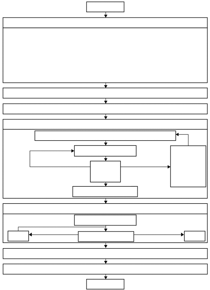
The adjustment should be performed according to the procedures referenced in the work flow below.
3. PREPARATION WORK
- NOTICE:
-
If the continuously variable transaxle assembly is hot (fluid temperature is high), wait until the fluid temperature becomes the same as the ambient temperature before starting the following procedure (recommended fluid temperature: approximately 20°C (68°F)).
Lift the vehicle.
- NOTICE:
-
Set the vehicle on a lift so that the vehicle is kept level when it is lifted up (make sure that the tilt angle from the front to rear and side to side of the vehicle is within +/- 1°).
Remove the No. 2 engine under cover assembly.
4.PERFORM INITIAL FILLING
- NOTICE:
-
After performing any of the following operations, it is not necessary to perform the initial filling procedure. Proceed to the Add Specified Amount of Fluid procedure (Step 5).
Operations that do not Require Initial Filling ·Removal and installation of the transmission oil cooler.
·Repair of a fluid leak, etc.
·Installation of a new continuously variable transaxle assembly (with new torque converter assembly).
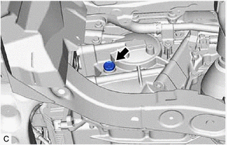
Remove the refill plug and gasket from the rear transaxle case sub-assembly.
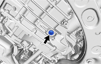
Using a 10 mm hexagon socket wrench, remove the overflow plug and gasket from the transaxle case sub-assembly.
- NOTICE:
- ·
If fluid comes out after removing the overflow plug, wait until the fluid flow slows and only drops come out.
·If fluid comes out, it is not necessary to perform the initial filling procedure. After checking the tightening torque of the overflow (CVT) tube, temporarily install the overflow plug.
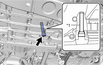
| *1 | Overflow (CVT) Tube |
Using a 6 mm hexagon socket wrench, check that the overflow (CVT) tube is tightened to the specified torque.
- Torque:
- 0.8 N*m (8 kgf*cm, 7 in.*lbf)
- NOTICE:
-
If the overflow (CVT) tube is not tightened to the specified torque, the amount of fluid cannot be precisely adjusted.
- HINT:
-
To check the torque of the overflow (CVT) tube, insert a 6 mm hexagon socket wrench into the overflow plug hole.
Perform initial filling.
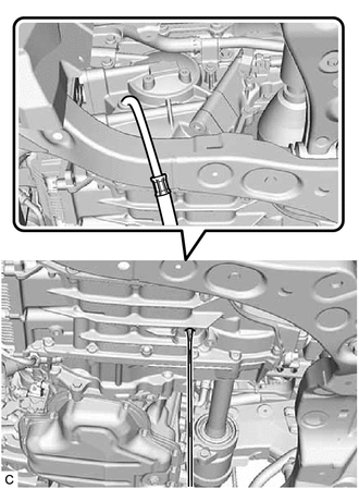
Add fluid to the refill plug hole until it flows out of the overflow plug hole.
- NOTICE:
-
Use Toyota Genuine CVT fluid FE.
-
Using CVT (Continuously Variable Transaxle) fluid other than the above type may cause abnormal noise or vibration, or damage the CVT (Continuously Variable Transaxle) of the vehicle.
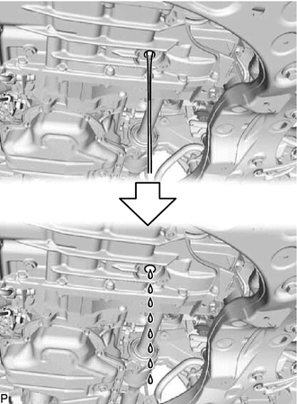
Wait until the fluid flow slows and only drips come out.
Using a 10 mm hexagon socket wrench, temporarily install the overflow plug and gasket to the transaxle case sub-assembly.
- HINT:
-
Reuse the old gasket as the overflow plug will be removed again to adjust the fluid level.
Temporarily install the refill plug and gasket to the rear transaxle case sub-assembly.
- HINT:
-
Reuse the old gasket as the refill plug will be removed again to adjust the fluid level.
5.ADD SPECIFIED AMOUNT OF FLUID
Remove the refill plug and gasket from the rear transaxle case sub-assembly.

Add fluid to the refill plug hole using the correct amount of fluid as listed in the table below.
- NOTICE:
-
Use Toyota Genuine CVT fluid FE.
-
Using CVT (Continuously Variable Transaxle) fluid other than the above type may cause abnormal noise or vibration, or damage the CVT (Continuously Variable Transaxle) of the vehicle.
- HINT:
-
The refill amount differs depending on the operation that was performed.
| Operation Performed | Fill Amount | |
|---|---|---|
| Replacement of the continuously variable transaxle assembly (without torque converter assembly or rebuilt transaxle) | (A new torque converter assembly has been installed) | 5.0 liters (5.3 US qts, 4.4 Imp. qts) |
| (The old torque converter assembly has been reused) | 4.5 liters (4.8 US qts, 4.0 Imp. qts) | |
| Removal and installation of the transaxle side cover sub-assembly | 2.0 liters (2.1 US qts, 1.8 Imp. qts) | |
| Removal and installation of the front drive shaft assembly | 3.0 liters (3.2 US qts, 2.6 Imp. qts) | |
| Removal and installation of the torque converter assembly | 2.5 liters (2.6 US qts, 2.2 Imp. qts) | |
| Removal and installation of the transmission oil cooler | 0.6 liters (0.6 US qts, 0.5 Imp. qts) | |
| Repair of a fluid leak, etc. | 0.6 liters (0.6 US qts, 0.5 Imp. qts) | |
Temporarily install the refill plug and gasket to the rear transaxle case sub-assembly to avoid fluid spillage.
- HINT:
-
Reuse the old gasket as the refill plug will be removed again to adjust the fluid level.
Lower the vehicle.
6.BLEED AIR FROM OIL PUMP ASSEMBLY
7.ADJUST FLUID TEMPERATURE (when Using the GTS)
- NOTICE:
-
To reduce load, make sure that all electrical systems, such as the air conditioning, lighting system, electric fan and audio system, are off.
- Powertrain > Engine > Active Test
-
Active Test Display Activate the TC Terminal -
Data List Display A/T Oil Temperature No.1 - 50004 372 22 180
According to the display on the GTS, perform the Active Test "Activate the TC Terminal / ON".
- HINT:
-
The indicator lights on the combination meter blink to indicate that a DTC has been stored when the Active Test "Activate the TC Terminal" is performed.
Depress and hold the brake pedal.
Start the engine.
Slowly move the shift lever from P to D, and then back to P (keep the shift lever in each position for approximately 3 seconds).
- HINT:
-
Slowly move the shift lever to circulate the fluid through each part of the continuously variable transaxle assembly.
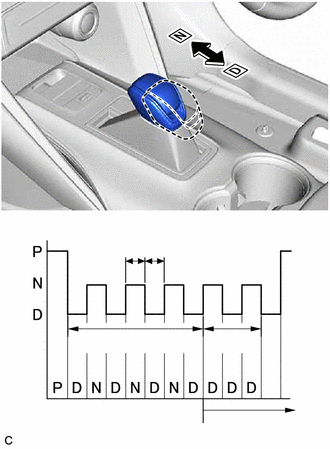
| *a | Shift Position |
| *b | Indication of Shift Position |
| *c | Fluid Temperature Detection Mode |
| *d | 6 sec. or more |
| *e | 2 sec. |
| *f | Less than 1.5 sec. |
While observing the D shift indicator on the combination meter, move the shift lever back and forth between N and D at an interval of less than 1.5 seconds for 6 seconds or more.
- NOTICE:
-
Do not pause for 1.5 seconds or more.
- HINT:
-
Performing this operation will cause the vehicle to enter fluid temperature detection mode.
Check that the D shift indicator comes on for 2 seconds.
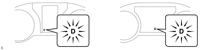
| *A | Type A | *B | Type B |
- HINT:
- ·
When fluid temperature detection mode is activated, the D shift indicator on the combination meter comes on for 2 seconds.
·If the D shift indicator does not come on for 2 seconds, return to the first step (perform the Active Test "Activate the TC Terminal / ON") and perform the procedure again.
Move the shift lever to P.
Release the brake pedal.
According to the display on the GTS, perform the Active Test "Activate the TC Terminal / OFF".
- NOTICE:
-
Make sure that terminals are not connected. If the terminals are connected, the fluid level cannot be precisely adjusted due to fluctuations in engine speed.
- HINT:
- ·
Disconnecting the terminals activates engine idle speed control mode.
·In engine idle speed control mode, engine idle speed control starts when the fluid temperature reaches the specified temperature and the engine speed is maintained.
·Even after the terminals are disconnected, fluid temperature detection mode remains active until the ignition switch is turned off.
Adjust the fluid temperature to the fluid level adjustment temperature.
Check the fluid temperature by monitoring the D shift indicator.
- Relationship between Fluid Level Adjustment Temperature and the D Shift Indicator:
Below Fluid Level Adjustment Temperature Fluid Level Adjustment Temperature Above Fluid Level Adjustment Temperature Fluid Temperature ("A/T Oil Temperature No.1" displayed on the GTS) 35°C (95°F) or less 35 to 45°C (95 to 113°F) 45°C (113°F) or more D Shift Indicator Off On Blinks
- HINT:
- ·
In fluid temperature detection mode, the D shift indicator comes on, goes off, or blinks depending on the fluid temperature.
·The fluid filling procedure should be performed when the D shift indicator is on (the fluid temperature is within the fluid level adjustment temperature range).
If the D shift indicator is on [Fluid Level Adjustment Temperature: 35 to 45°C (95 to 113°F)]: Immediately proceed to the Adjust Fluid Level (Step 9).
Adjust the fluid temperature.
If the D shift indicator is off [Below Fluid Level Adjustment Temperature: 35°C (95°F) or less]: Warm up the engine with the engine idling in engine idle speed control mode until the D shift indicator turns on.
If the D shift indicator is on [Fluid Level Adjustment Temperature: 35 to 45°C (95 to 113°F)]: Immediately proceed to the Adjust Fluid Level (Step 9).
If the D shift indicator is blinking [Above Fluid Level Adjustment Temperature: 45°C (113°F) or more]: Stop the engine and wait until the fluid temperature drops to 35°C (95°F) or less (the D shift indicator goes off). Then perform the adjust fluid temperature procedure again from the beginning.
8.ADJUST FLUID TEMPERATURE (when Not Using the GTS)
Turn the ignition switch off.
Depress and hold the brake pedal.
Start the engine. [#1]
- NOTICE:
-
To reduce load, make sure that all electrical systems, such as the air conditioning, lighting system, electric fan and audio system, are off.
Slowly move the shift lever from P to D, and then back to P (keep the shift lever in each position for approximately 3 seconds). [#2]
- HINT:
-
Slowly move the shift lever to circulate the fluid through each part of the continuously variable transaxle assembly.
| *a | Shift Position |
| *b | Indication of Shift Position |
| *c | Fluid Temperature Detection Mode |
| *d | 12 sec. or more |
| *e | 2 sec. |
| *f | Less than 1.5 sec. |
While observing the D shift indicator on the combination meter, move the shift lever back and forth between N and D at an interval of less than 1.5 seconds for 12 seconds or more. [#3]
- NOTICE:
-
Do not pause for 1.5 seconds or more.
- HINT:
- ·
Performing this operation will cause the vehicle to enter fluid temperature detection mode and engine idle speed control mode.
·In engine idle speed control mode, engine idle speed control starts when the fluid temperature reaches the specified temperature and the engine speed is maintained.
·Perform [#1] to [#3] within 60 seconds.
Check that the D shift indicator comes on for 2 seconds.
| *A | Type A | *B | Type B |
- HINT:
- ·
When fluid temperature detection mode is activated, the D shift indicator on the combination meter comes on for 2 seconds.
·If the D shift indicator does not come on for 2 seconds, return to the first step (Start the engine. [#1]) and perform the procedure again.
·Fluid temperature detection mode is active until the ignition switch is turned off.
Move the shift lever to P.
Release the brake pedal.
Adjust the fluid temperature to the fluid level adjustment temperature.
Check the fluid temperature by monitoring the D shift indicator.
- Relationship between Fluid Level Adjustment Temperature and the D Shift Indicator:
Below Fluid Level Adjustment Temperature Fluid Level Adjustment Temperature Above Fluid Level Adjustment Temperature Fluid Temperature 35°C (95°F) or less 35 to 45°C (95 to 113°F) 45°C (113°F) or more D Shift Indicator Off On Blinks
- HINT:
- ·
In fluid temperature detection mode, the D shift indicator comes on, goes off, or blinks depending on the fluid temperature.
·The fluid filling procedure should be performed when the D shift indicator is on (the fluid temperature is within the fluid level adjustment temperature range).
If the D shift indicator is on [Fluid Level Adjustment Temperature: 35 to 45°C (95 to 113°F)]: Immediately proceed to the Adjust Fluid Level (Step 9).
Adjust the fluid temperature.
If the D shift indicator is off [Below Fluid Level Adjustment Temperature: 35°C (95°F) or less]: Warm up the engine with the engine idling in engine idle speed control mode until the D shift indicator turns on.
If the D shift indicator is on [Fluid Level Adjustment Temperature: 35 to 45°C (95 to 113°F)]: Immediately proceed to Adjust Fluid Level (Step 9).
If the D shift indicator is blinking [Above Fluid Level Adjustment Temperature: 45°C (113°F) or more]: Stop the engine and wait until the fluid temperature drops to 35°C (95°F) or less (the D shift indicator goes off). Then perform the adjust fluid temperature procedure again from the beginning.
9.ADJUST FLUID LEVEL
- CAUTION:
- ·
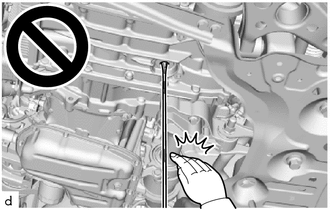
Make sure not to get any of the drained fluid on your hands, etc.
·The high temperature of the drained fluid could cause burns.
·
When working near the engine room while the engine has started or the ignition switch is ON, do not touch the rotating components such as the V-ribbed belt or cooling fan.
·Touching the rotating components such as the V-ribbed belt or cooling fan could result in your hand or clothing getting caught and pulled in.
Lift the vehicle.
- NOTICE:
-
Set the vehicle on a lift so that the vehicle is kept level when it is lifted up (make sure that the tilt angle from the front to rear and side to side of the vehicle is within +/-1°).
Using a 10 mm hexagon socket wrench, remove the overflow plug and gasket from the transaxle case sub-assembly.
- CAUTION:
-
Be careful as the fluid coming out of the overflow plug hole is hot.
Check the amount of fluid that comes out of the overflow plug hole.
If the amount of fluid that comes out of the overflow plug hole is large, proceed to step [#1].
If no fluid comes out of the overflow plug hole, proceed to step [#2].
- NOTICE:
-
If only a small amount of fluid (approximately 5 cc) comes out of the overflow plug hole, then only fluid remaining in the overflow (CVT) tube has come out. This condition is not considered as overflow, so it is necessary to add fluid.
If the amount of fluid that comes out of the overflow plug hole is large. [#1]
Wait until the fluid flow slows and only drips come out.
- HINT:
-
The fluid flow will not stop completely because the fluid continues to expand as its temperature increases.
If no fluid comes out of the overflow plug hole. [#2]
Remove the refill plug and gasket from the rear transaxle case sub-assembly.
Then add fluid through the refill plug hole until fluid comes out of the overflow plug hole.
- NOTICE:
-
Use Toyota Genuine CVT fluid FE.
-
Using CVT (Continuously Variable Transaxle) fluid other than the above type may cause abnormal noise or vibration, or damage the CVT (Continuously Variable Transaxle) of the vehicle.
Wait until the fluid flow slows and only drips come out.
- HINT:
-
The fluid flow will not stop completely because the fluid continues to expand as its temperature increases.
Coat a new gasket with Toyota Genuine CVT fluid FE and install it to the overflow plug.
Using a 10 mm hexagon socket wrench, install the overflow plug to the transaxle case sub-assembly.
- Torque:
- 49 N*m (500 kgf*cm, 36 ft.*lbf)
- NOTICE:
-
To prevent the gasket from being deformed when tightening, coat it with Toyota Genuine CVT fluid FE.
Coat a new gasket with Toyota Genuine CVT fluid FE and install it to the refill plug.
Install the refill plug to the rear transaxle case sub-assembly.
- Torque:
- 49 N*m (500 kgf*cm, 36 ft.*lbf)
- NOTICE:
-
To prevent the gasket from being deformed when tightening, coat it with Toyota Genuine CVT fluid FE.
Lower the vehicle.
Turn the ignition switch off.
- HINT:
-
Turning the ignition switch off ends fluid temperature detection mode.
Disconnect the GTS from the DLC3 (when using the GTS).
10.PERFORM ATF THERMAL DEGRADATION ESTIMATE RESET
- NOTICE:
-
If approximately 50% or more of the CVT fluid has been replaced during a repair of the transaxle or a similar operation, perform ATF Thermal Degradation Estimate Reset.
11. REBUILD WORK
Lift the vehicle.
Clean each part.
Check for fluid leaks.
Install the No. 2 engine under cover assembly.
Lower the vehicle.