M20C-FKS, M20D-FKS ENGINE MECHANICAL CAMSHAFT REMOVAL
CAUTION / NOTICE / HINT
The necessary procedures (adjustment, calibration, initialization or registration) that must be performed after parts are removed and installed, or replaced during camshaft removal/installation are shown below.
| Replaced Part or Performed Procedure | Necessary Procedure | Effect/Inoperative Function when Necessary Procedure not Performed | Link |
|---|---|---|---|
|
*: Even when not replacing the part, it is necessary to perform the specified necessary procedures afterinstallation. |
|||
| Battery terminal is disconnected/reconnected | Reset back door close position | Power Back Door System | ( 202111,999999,_59,_111831,_0505274,RM100000001ZMEG,) 202111,999999,_59,_111831,_0505274,RM100000001ZMEG,)
|
·
Replacement of throttle body with motor assembly ·
Cleaning the deposits from the throttle body with motor assembly ·
Replacement of cam timing control motor with EDU assembly* ·
Replacement of camshaft timing gear assembly* ·
Replacement of camshaft (for intake or exhaust camshaft) ·
Replacement of camshaft timing exhaust gear assembly ·
Replacement of fuel pump assembly (for high pressure side) ·
Replacement of ignition coil assembly ·
Replacement of EGR valve assembly ·
Gas leak from exhaust system is repaired |
Inspection after repair | ·
Poor idle, etc. ·
Engine start function, etc. |
(202303,999999,_51,_111785,_0504416,RM1000000029BFF,)
|
- HINT:
-
When the cable is disconnected / reconnected to the battery terminal, systems temporarily stop operating. However, each system has a function that completes learning the first time the system is used.
Items for which learning is completed by driving the vehicle Effect/Inoperative Function when Necessary Procedure not Performed Necessary Procedure Link Lane Tracing Assist System Drive the vehicle straight ahead at 15 km/h (10 mph) or more for 1 seconds or more. ( 202111,999999,_95,_111850,_0502173,RM100000001Z92I,)
Pre-collision System Stop and Start System dle the engine for approximately 5 to 60minutes or drive the vehicle until stop andstart control is permitted ( 202406,999999,_51,_111803,_0509671,RM100000002KOGF,)
Items for which learning is completed by operating the vehicle normally Effect/Inoperative Function when Necessary Procedure not Performed Necessary Procedure Link Power Door Lock Control System
·Back door opener
Perform door unlock operation with door control switch or electrical key transmitter sub-assembly switch. ( 202111,999999,_58,_111830,_0505351,RM100000001ZMT3,)
Air Conditioning System After the ignition switch is turned to ON, the servo motor standard position is recognized. -
- NOTICE:
-
This procedure includes the removal of small-head bolts. Refer to Small-Head Bolts of Basic Repair Hint to identify the small-head bolts.
PROCEDURE

 23100X
1.REMOVE FUEL (ENGINE ROOM SIDE) PUMP ASSEMBLY (for High Pressure)
23100X
1.REMOVE FUEL (ENGINE ROOM SIDE) PUMP ASSEMBLY (for High Pressure)
29300
2.REMOVE VACUUM PUMP ASSEMBLY
for M20 Series Engine, BOSCH Made:
for M20 Series Engine, except BOSCH Made:
19500
3.REMOVE IGNITION COIL ASSEMBLY
15370
4.REMOVE CAM TIMING OIL CONTROL SOLENOID ASSEMBLY
5.REMOVE O-RING
135A0B
6.REMOVE CAMSHAFT TIMING VALVE ASSEMBLY
82286A
7.SEPARATE NO. 2 EARTH WIRE
13090D
8.REMOVE CAM TIMING CONTROL MOTOR WITH EDU ASSEMBLY
13090E
9.REMOVE CAM TIMING CONTROL MOTOR O-RING
11102A
10.REMOVE CAMSHAFT POSITION SENSOR (for Intake Side)
11102A
11.REMOVE CAMSHAFT POSITION SENSOR (for Exhaust Side)
11201
12.REMOVE CYLINDER HEAD COVER SUB-ASSEMBLY
11193
13.REMOVE SPARK PLUG TUBE GASKET
23477
14.REMOVE FUEL PUMP LIFTER GUIDE
15.SET NO. 1 CYLINDER TO TDC (COMPRESSION)
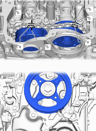
| *a | Paint Mark |
| *b | Timing Mark |
| *c | "0" Timing Mark |
Turn the crankshaft clockwise to align the timing mark (cutout) on the crankshaft pulley assembly with the "0" timing mark on the No. 2 timing chain cover assembly.
Check that the timing marks are positioned as shown in the illustration.
- HINT:
-
If the timing marks are not positioned as shown in the illustration, turn the crankshaft clockwise and then align them again.
Place paint marks on the chain sub-assembly at points aligned with the timing marks on the camshaft timing gear assembly and camshaft timing exhaust gear assembly.
16.REMOVE STRAIGHT SCREW PLUG
17.REMOVE CAMSHAFT
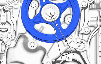
| *a | Approximately 15° |
Rotate the crankshaft approximately 15° clockwise.
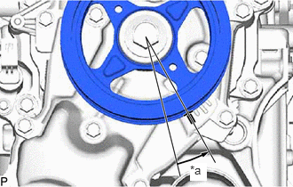
| *a | Approximately 15° |
Rotate the crankshaft approximately 15° counterclockwise.
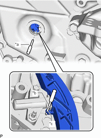
| *a | Pin |
| *b | Pin Hole (No. 1 Chain Tensioner Assembly Side) |
| *c | Pin Hole (Chain Tensioner Slipper Side) |
Align the pin hole of the No. 1 chain tensioner assembly with the pin hole of the chain tensioner slipper, and then insert the pin.
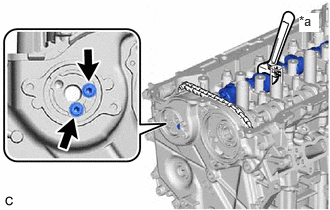
| *a | Hold |
Using the hexagonal portion of the exhaust camshaft sub-assembly, secure the exhaust camshaft sub-assembly.
- NOTICE:
-
Do not damage the camshaft housing sub-assembly, cylinder head sub-assembly and spark plug tube.
Using a 5 mm hexagon socket wrench, remove the 2 bolts from the camshaft timing exhaust gear assembly.
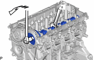
| *a | Hold |

|
Turn |
Using the hexagonal portion of the intake camshaft sub-assembly, secure the intake camshaft sub-assembly.
- NOTICE:
- ·
Do not damage the camshaft housing sub-assembly, cylinder head sub-assembly and spark plug tube.
·Do not disassemble the camshaft timing gear assembly.
Using a 10 mm bi-hexagon socket wrench, remove the bolt from the camshaft timing gear assembly.
Using the hexagonal portion of the exhaust camshaft sub-assembly, loosen and hold the chain sub-assembly while moving the exhaust camshaft sub-assembly in the direction shown in the illustration.
- NOTICE:
-
Do not damage the camshaft housing sub-assembly, cylinder head sub-assembly and spark plug tube.
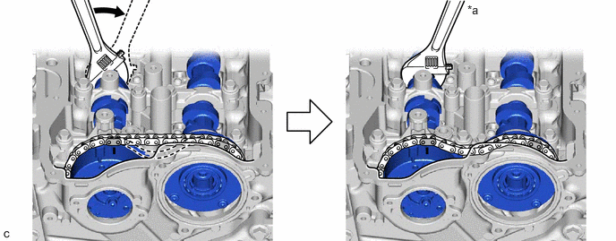
| *a | Hold | - | - |

|
Turn | - | - |
Move the camshaft timing gear assembly together with the camshaft timing exhaust gear assembly and chain sub-assembly toward the No. 2 timing chain cover assembly as shown in the illustration.
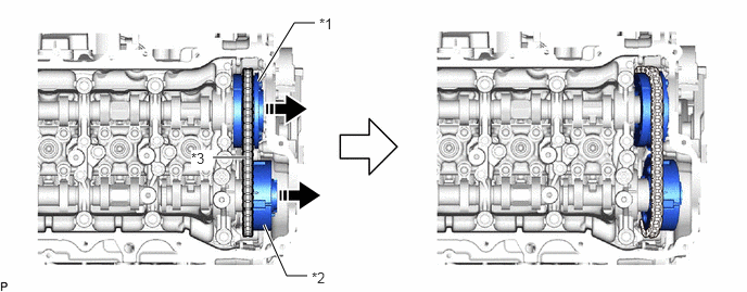
| *1 | Camshaft Timing Gear Assembly | *2 | Camshaft Timing Exhaust Gear Assembly |
| *3 | Chain Sub-assembly | - | - |
|
|
Remove in this Direction | - | - |
Remove the camshaft timing exhaust gear assembly from the chain sub-assembly.
Remove the camshaft timing gear assembly from the chain sub-assembly.
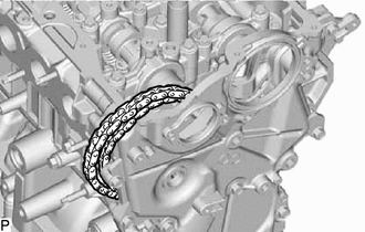
Secure the chain sub-assembly to the vehicle using rope, etc.
- NOTICE:
-
Do not drop the chain sub-assembly into the timing chain cover assembly.
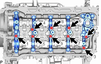
Uniformly loosen and remove the 9 bolts in the order shown in the illustration.
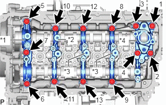
| *1 | No. 1 Camshaft Bearing Cap |
| *2 | No. 2 Camshaft Bearing Cap |
| *3 | No. 3 Camshaft Bearing Cap |
| *4 | No. 4 Camshaft Bearing Cap |
Uniformly loosen and remove the 13 bolts in the order shown in the illustration.
- NOTICE:
-
Uniformly loosen the bolts while holding the camshaft horizontally.
Remove the No. 1 camshaft bearing cap, No. 2 camshaft bearing cap, 2 No. 3 camshaft bearing caps and No. 4 camshaft bearing cap.
- HINT:
-
Arrange the removed parts so that they can be reinstalled in their original locations.
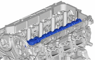
Remove the intake camshaft sub-assembly from the camshaft housing sub-assembly.
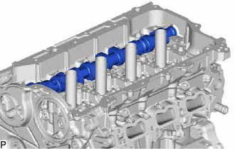
Remove the exhaust camshaft sub-assembly from the camshaft housing sub-assembly.