DOOR / HATCH POWER BACK DOOR SYSTEM Power Back Door does not Operate Using Outside Switch
DESCRIPTION
The multiplex network door ECU detects the status of the power back door control switch.
If the power back door does not operate when the power back door control switch is operated, there may be a malfunction in the power back door control switch circuit.
WIRING DIAGRAM
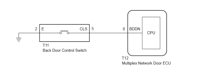
CAUTION / NOTICE / HINT
- NOTICE:
-
If the replacement, removal and installation of the multiplex network door ECU or disconnection of the connectors of the multiplex network door ECU has been performed, initialize the power back door system.
PROCEDURE
Read the Data List according to the display on the GTS.
- Body Electrical > Back Door > Data List
-
Tester Display Measurement Item Range Normal Condition Diagnostic Note PBD Close Switch Power back door control switch assembly signal ON or OFF ON: Back door control switch assembly pushed
OFF: Back door control switch assembly not pushed-
- Body Electrical > Back Door > Data List
-
Tester Display PBD Close Switch - 50003 489 1038
- OK:
The display is as specified in the normal condition column.
- Result:
Proceed to OK NG
OK
NG
- Result:
Proceed to OK NG
OK
NG
Disconnect the T12 multiplex network door ECU connector.
Measure the resistance according to the value(s) in the table below.
- Standard Resistance:
Tester Connection Condition Specified Condition Click Location & Routing(T11,T12)Location & Routingewd_type=routing;type=c,c;code=T11,T12
Click Connector(T11)Body>No. 1 Back Door Wire>Back Door Control Switchewd_type=component;type=c;code=T11;pinno=5,2
Click Connector(T12)Body>No. 1 Back Door Wire>Multiplex Network Door ECUewd_type=component;type=c;code=T12;pinno=8
T11-5 (CLS) - T12-8 (BDDN) Always Below 1 Ω T11-2 (E) - Body ground Always Below 1 Ω T11-5 (CLS) or T12-8 (BDDN) - Body ground Always 10 kΩ or higher
- Result:
Proceed to OK NG
OK
NG