DOOR / HATCH POWER BACK DOOR SYSTEM Power Back Door does not Operate Using Cabin Switch
DESCRIPTION
The power back door control switch signal is sent to the multiplex network door ECU via CAN communication.
If the power back door does not operate when the power back door control switch is operated, there may be a malfunction in the power back door control switch circuit.
WIRING DIAGRAM
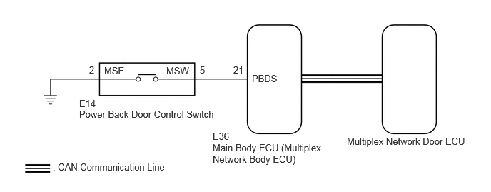
CAUTION / NOTICE / HINT
- NOTICE:
- ·
The power back door system uses the CAN communication system. Inspect the communication function by following How to Proceed with Troubleshooting. Troubleshoot the power back door system after confirming that the CAN communication system is functioning properly.
·If the replacement, removal and installation of the multiplex network door ECU or disconnection of the connectors of the multiplex network door ECU has been performed, initialize the power back door system.
·If the main body ECU (multiplex network body ECU) is replaced, refer to Service Bulletin.
PROCEDURE
Read the Data List according to the display on the GTS.
- Body Electrical > Main Body > Data List
-
Tester Display Measurement Item Range Normal Condition Diagnostic Note Back Door Operation Switch (Instrument) Power back door control switch signal OFF or ON OFF: Power back door control switch off
ON: Power back door control switch on-
- Body Electrical > Main Body > Data List
-
Tester Display Back Door Operation Switch (Instrument) - 50003 449 47
- OK:
The display is as specified in the normal condition column.
- Result:
Proceed to OK NG
OK
NG
- Result:
Proceed to OK NG
OK
NG
Disconnect the E36 main body ECU (multiplex network body ECU) connector.
Measure the resistance according to the value(s) in the table below.
- Standard Resistance:
Tester Connection Condition Specified Condition Click Location & Routing(E14,E36)Location & Routingewd_type=routing;type=c,c;code=E14,E36
Click Connector(E14)Instrument Panel>Instrument Panel Wire / Radio Wiring Sub-Assy / Telephone Computer Wire>Power Back Door Control Switchewd_type=component;type=c;code=E14;pinno=5,2
Click Connector(E36)Instrument Panel>Instrument Panel Wire / Radio Wiring Sub-Assy / Telephone Computer Wire>Multiplex Network Body ECUewd_type=component;type=c;code=E36;pinno=21
E14-5 (MSW) - E36-21 (PBDS) Always Below 1 Ω E14-2 (MSE) - Body ground Always Below 1 Ω E14-5 (MSW) or E36-21 (PBDS) - Body ground Always 10 kΩ or higher
- Result:
Proceed to OK NG
OK
NG