DOOR / HATCH POWER BACK DOOR SYSTEM B225101 Back Door Closer Switch General Electrical Failure
DESCRIPTION
The multiplex network door ECU receives signals from the latch switch, position switch, pawl switch and back door courtesy switch, which are built into the back door lock with courtesy light switch assembly. Based on these signals, the latch position of the back door lock with courtesy light switch assembly is determined.
| DTC No. | Detection Item | DTC Detection Condition | Trouble Area |
|---|---|---|---|
| B225101 | Back Door Closer Switch General Electrical Failure | While the back door closer is operating, a malfunction in the position information from the back door courtesy switch is detected within a certain amount of time. | ·
Back door lock with courtesy light switch assembly ·
Multiplex network door ECU ·
Wire harness or connector |
WIRING DIAGRAM
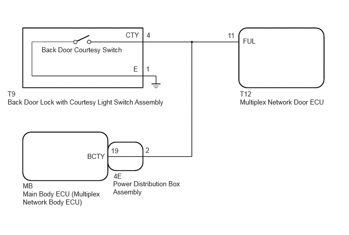
CAUTION / NOTICE / HINT
- NOTICE:
-
If the multiplex network door ECU has been removed and installed or replaced, or if any of the connectors have been disconnected, initialize the power back door system.
PROCEDURE
Read the Data List according to the display on the GTS.
- Body Electrical > Back Door > Data List
-
Tester Display Measurement Item Range Normal Condition Diagnostic Note Courtesy Switch Back door courtesy switch signal ON or OFF ON: Back door open
OFF: Back door closed-
- Body Electrical > Back Door > Data List
-
Tester Display Courtesy Switch - 50003 489 1018
- OK:
The display is as specified in the normal condition column.
- Result:
Proceed to OK NG
OK
NG
- Result:
Proceed to OK NG
OK
NG
Click hereVehicle Interior>DOOR LOCK>BACK DOOR LOCK>REMOVAL202111,999999,_58,_111830,_0501509,RM100000001Z6GX,
Disconnect the 4E power distribution box assembly connector.
Measure the resistance according to the value(s) in the table below.
- Standard Resistance:
Tester Connection Condition Specified Condition Click Location & Routing(T9,T12)Location & Routingewd_type=routing;type=c,c;code=T9,T12
Click Connector(T9)Body>No. 1 Back Door Wire>Back Door Lock Assembly with Courtesy Light Switchewd_type=component;type=c;code=T9;pinno=4,1
Click Connector(T12)Body>No. 1 Back Door Wire>Multiplex Network Door ECUewd_type=component;type=c;code=T12;pinno=11
T9-4 (CTY) - T12-11 (FUL) Always Below 1 Ω T9-1 (E) - Body ground Always Below 1 Ω T9-4 (CTY) or T12-11 (FUL) - Body ground Always 10 kΩ or higher
- Result:
Proceed to OK NG
OK
NG