METER / GAUGE / DISPLAY METER / GAUGE SYSTEM(for TFT Meter Type) B150819 Turn Signal/Hazard Flasher Circuit Current Above Threshold
DESCRIPTION
This DTC is stored when the combination meter assembly detects a short in a turn signal light circuit.
- HINT:
-
If there is a short in a turn signal light circuit, the turn signal lights on the side with the short circuit will blink faster than usual.
| DTC No. | Detection Item | DTC Detection Condition | Trouble Area | DTC Output from | Priority |
|---|---|---|---|---|---|
| B150819 | Turn Signal/Hazard Flasher Circuit Current Above Threshold | Diagnosis Condition:
Battery voltage is 10 V or more Malfunction Status: Short in turn signal light circuit |
·
Headlight assembly ·
Outer rear view mirror assembly -
Side turn signal light assembly ·
Rear turn signal light assembly ·
Harness or connector ·
Combination meter assembly |
Combination Meter | A |
WIRING DIAGRAM
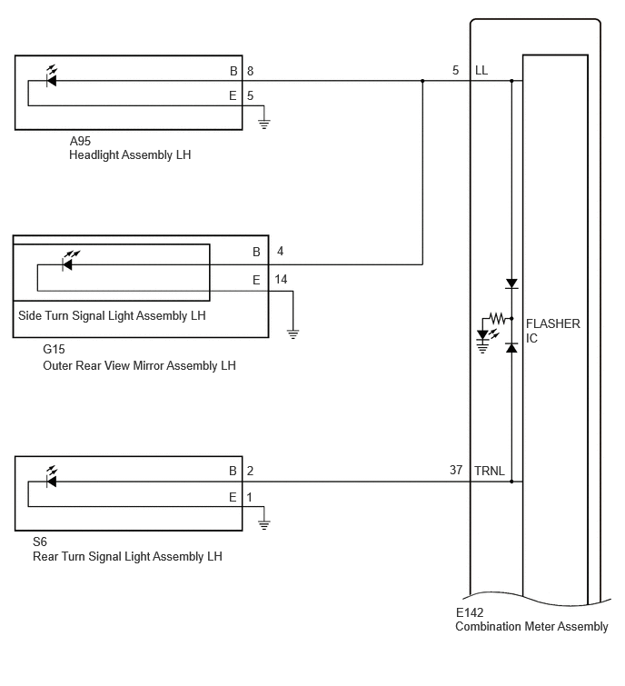
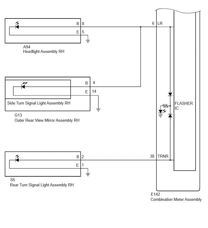
CAUTION / NOTICE / HINT
- NOTICE:
- ·
When replacing the combination meter assembly, always replace it with a new one. If a combination meter assembly which was installed to another vehicle is used, the information stored in it will not match the information from the vehicle and a DTC may be stored.
·When replacing the combination meter assembly, update the ECU security key.
PROCEDURE
Operate the turn signal switch and check the problem symptoms.
- Result:
Result Proceed to Front turn signal light (LH side) does not blink A Side turn signal light (LH side) does not blink B Rear turn signal light (LH side) does not blink C Front turn signal light (RH side) does not blink D Side turn signal light (RH side) does not blink E Rear turn signal light (RH side) does not blink F
A
B
C
D
E
F
Pre-procedure1
Remove the headlight assembly LH.
Remove the headlight assembly RH.
Interchange the headlight assembly LH with RH and connect the connectors.
Procedure1
Check the front turn signal light (LH side) operates normally.
- Result:
Result Proceed to Problem symptoms do not change
(Front turn signal light (LH side) does not blink)A Front turn signal light (LH side) operates normally B
Post-procedure1
None
A
B
Pre-procedure1
Remove the outer rear view mirror assembly LH.
Remove the outer rear view mirror assembly RH.
Interchange the outer rear view mirror assembly LH with RH and connect the connectors.
Procedure1
Check the side turn signal light (LH side) operates normally.
- Result:
Result Proceed to Problem symptoms do not change
(Front/side turn signal light (LH side) does not blink)A Front/side turn signal light (LH side) operates normally B
Post-procedure1
None
A
B
Pre-procedure1
Disconnect the A95 headlight assembly LH connector.
Disconnect the G15 outer rear view mirror assembly LH connector.
Disconnect the E142 combination meter assembly connector.
Procedure1
Measure the resistance according to the value(s) in the table below.
- Standard Resistance:
Tester Connection Condition Specified Condition Click Location & Routing(A95,G15,E142)Location & Routingewd_type=routing;type=c,c,c;code=A95,G15,E142
Click Connector(A95)Engine Compartment>Engine Room Main Wire / Transmission Wire>Headlight Assembly LHewd_type=component;type=c;code=A95;pinno=8
Click Connector(G15)Body>Front Door Wire RH / Front Door Wire LH>Outer Rear View Mirror Assembly LHewd_type=component;type=c;code=G15;pinno=4
Click Connector(E142)Instrument Panel>Instrument Panel Wire / Telephone Computer Wire>Combination Meter Assemblyewd_type=component;type=c;code=E142;pinno=5
A95-8 (B), G15-4 (B) or E142-5 (LL) - Body ground Always 10 kΩ or higher
- Result:
Proceed to OK NG
Post-procedure1
None
OK
NG
Pre-procedure1
Remove the side turn signal light assembly LH from the outer rear view mirror assembly LH.
Remove the side turn signal light assembly RH from the outer rear view mirror assembly RH.
Interchange the side turn signal light assembly LH with RH and connect the connectors.
Procedure1
Check the side turn signal light (LH side) operates normally.
- Result:
Result Proceed to Front/side turn signal light (LH side) operates normally A Front/side turn signal light (LH side) does not blink B
Post-procedure1
None
A
B
Pre-procedure1
Remove the rear turn signal light assembly LH.
Remove the rear turn signal light assembly RH.
Interchange the rear turn signal light assembly LH with RH and connect the connectors.
Procedure1
Check the rear turn signal light (LH side) operates normally.
- Result:
Result Proceed to Problem symptoms do not change
(Rear turn signal light (LH side) does not blink)A Rear turn signal light (LH side) operates normally B
Post-procedure1
None
A
B
Pre-procedure1
Disconnect the S6 rear turn signal light assembly LH connector.
Disconnect the E142 combination meter assembly connector.
Procedure1
Measure the resistance according to the value(s) in the table below.
- Standard Resistance:
Tester Connection Condition Specified Condition Click Location & Routing(S6,E142)Location & Routingewd_type=routing;type=c,c;code=S6,E142
Click Connector(S6)Body>No. 2 Luggage Room Wire / No. 3 Luggage Room Wire>Rear Turn Signal Light Assembly LHewd_type=component;type=c;code=S6;pinno=2
Click Connector(E142)Instrument Panel>Instrument Panel Wire / Telephone Computer Wire>Combination Meter Assemblyewd_type=component;type=c;code=E142;pinno=37
S6-2 (B) or E142-37 (TRNL) - Body ground Always 10 kΩ or higher
- Result:
Proceed to OK NG
Post-procedure1
None
OK
NG
Pre-procedure1
Remove the headlight assembly RH.
Remove the headlight assembly LH.
Interchange the headlight assembly RH with LH and connect the connectors.
Procedure1
Check the front turn signal light (RH side) operates normally.
- Result:
Result Proceed to Problem symptoms do not change
(Front turn signal light (RH side) does not blink)A Front turn signal light (RH side) operates normally B
Post-procedure1
None
A
B
Pre-procedure1
Remove the outer rear view mirror assembly RH.
Remove the outer rear view mirror assembly LH.
Interchange the outer rear view mirror assembly RH with LH and connect the connectors.
Procedure1
Check the side turn signal light (RH side) operates normally.
- Result:
Result Proceed to Problem symptoms do not change
(Front/side turn signal light (RH side) does not blink)A Front/side turn signal light (RH side) operates normally B
Post-procedure1
None
A
B
Pre-procedure1
Disconnect the A94 headlight assembly RH connector.
Disconnect the G13 outer rear view mirror assembly RH connector.
Disconnect the E142 combination meter assembly connector.
Procedure1
Measure the resistance according to the value(s) in the table below.
- Standard Resistance:
Tester Connection Condition Specified Condition Click Location & Routing(A94,G13,E142)Location & Routingewd_type=routing;type=c,c,c;code=A94,G13,E142
Click Connector(A94)Engine Compartment>Engine Room Main Wire / Transmission Wire>Headlight Assembly RHewd_type=component;type=c;code=A94;pinno=8
Click Connector(G13)Body>Front Door Wire RH / Front Door Wire LH>Outer Rear View Mirror Assembly RHewd_type=component;type=c;code=G13;pinno=4
Click Connector(E142)Instrument Panel>Instrument Panel Wire / Telephone Computer Wire>Combination Meter Assemblyewd_type=component;type=c;code=E142;pinno=6
A94-8 (B), G13-4 (B) or E142-6 (LR) - Body ground Always 10 kΩ or higher
- Result:
Proceed to OK NG
Post-procedure1
None
OK
NG
Pre-procedure1
Remove the side turn signal light assembly RH from the outer rear view mirror assembly RH.
Remove the side turn signal light assembly LH from the outer rear view mirror assembly LH.
Interchange the side turn signal light assembly RH with LH and connect the connectors.
Procedure1
Check the side turn signal light (RH side) operates normally.
- Result:
Result Proceed to Front/side turn signal light (RH side) operates normally A Front/side turn signal light (RH side) does not blink B
Post-procedure1
None
A
B
Pre-procedure1
Remove the rear turn signal light assembly RH.
Remove the rear turn signal light assembly LH.
Interchange the rear turn signal light assembly RH with LH and connect the connectors.
Procedure1
Check the rear turn signal light (RH side) operates normally.
- Result:
Result Proceed to Problem symptoms do not change
(Rear turn signal light (RH side) does not blink)A Rear turn signal light (RH side) operates normally B
Post-procedure1
None
A
B
Pre-procedure1
Disconnect the S5 rear turn signal light assembly RH connector.
Disconnect the E142 combination meter assembly connector.
Procedure1
Measure the resistance according to the value(s) in the table below.
- Standard Resistance:
Tester Connection Condition Specified Condition Click Location & Routing(S5,E142)Location & Routingewd_type=routing;type=c,c;code=S5,E142
Click Connector(S5)Body>No. 2 Luggage Room Wire / No. 3 Luggage Room Wire>Rear Turn Signal Light Assembly RHewd_type=component;type=c;code=S5;pinno=2
Click Connector(E142)Instrument Panel>Instrument Panel Wire / Telephone Computer Wire>Combination Meter Assemblyewd_type=component;type=c;code=E142;pinno=38
S5-2 (B) or E142-38 (TRNR) - Body ground Always 10 kΩ or higher
- Result:
Proceed to OK NG
Post-procedure1
None
OK
NG